Generally speaking, in order to explain the performance of UPS products, UPS manufacturers indicate certain standards that their products have reached in the product manual or provide user-friendly performance indicators, which are usually given in the product indicators column.
UPS users can quickly understand the product overview by reading the indicator column in the product manual, which is necessary for equipment selection and maintenance. The following describes the input indicators, output indicators, UPS battery indicators and other indicators.

 Where, +… , represents 1,2… ,n times harmonic current effective value. If the phase difference between fundamental wave current and voltage is also assumed to be φ, the power factor PF can be expressed as:
 That is, the power factor of nonlinear circuit is the product of distortion factor and displacement factor (cosφ).The input power factor refers to the input power factor and the input current quality of the rectifier charger in the UPS.
It indicates the capability of the power supply to absorb active power from the power grid and the interference to the power grid.
The higher the input power factor is, the smaller the harmonic component content of the input current is, which indicates that the power supply has less pollution to the power grid.
That is, the power factor of nonlinear circuit is the product of distortion factor and displacement factor (cosφ).The input power factor refers to the input power factor and the input current quality of the rectifier charger in the UPS.
It indicates the capability of the power supply to absorb active power from the power grid and the interference to the power grid.
The higher the input power factor is, the smaller the harmonic component content of the input current is, which indicates that the power supply has less pollution to the power grid.
 The input power factor of the online UPS meets the requirements of Table 1-2. And the harmonic components of the input current meet the requirements of Table 1-3.

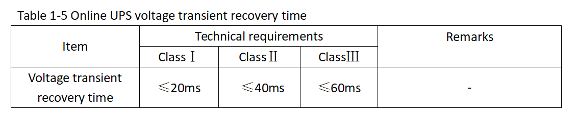
 ④ Transient voltage recovery time:
the time required for the output voltage to recover to (224±4.4) V when the input voltage is rated, the output current is resistive load, and the output current changes from zero to rated current or the rated current changes to zero.
The voltage transient recovery time of the backup and interactive UPS should be less than or equal to 60 Ms. The voltage transient recovery time of the online UPS should meet the requirements listed in Table 1-5.
④ Transient voltage recovery time:
the time required for the output voltage to recover to (224±4.4) V when the input voltage is rated, the output current is resistive load, and the output current changes from zero to rated current or the rated current changes to zero.
The voltage transient recovery time of the backup and interactive UPS should be less than or equal to 60 Ms. The voltage transient recovery time of the online UPS should meet the requirements listed in Table 1-5.
 ⑤ Output voltage frequency:
Range of frequency synchro refers to the range in which the UPS output frequency tracks the change of the input frequency during AC power supply.
The frequency tracking range of the UPS ranges from 48 Hz to 52Hz. The rate of frequency synchro indicates the rate at which the UPS output frequency tracks the input frequency if the UPS output frequency is different from the input AC frequency.
The rate is expressed in Hz/s. The UPS frequency tracking rate ranges from 0.5 – 2Hz/s. When working in the output state of the inverter, the ratio (stability) should not be wider than (50±0.5) Hz.
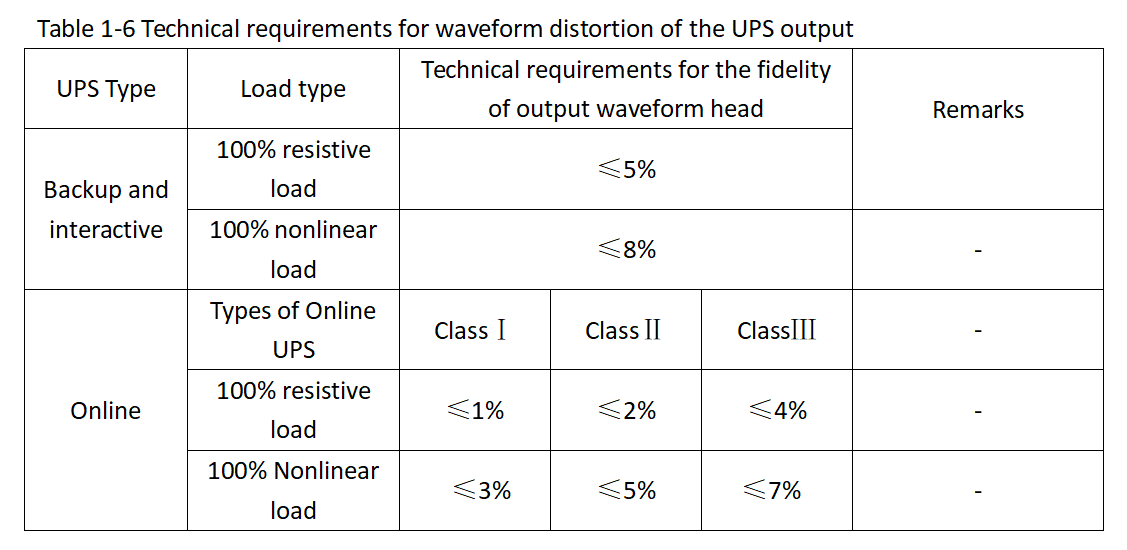
⑥ Output (voltage) waveform and distortion:
according to different uses, the output voltage is not necessarily sine wave, it can also be square wave or trapezoidal wave.
The output waveform of the backup UPS is usually square wave, and that of the online UPS is usually sine wave.
Waveform distortion is generally for the sinusoidal output UPS, refers to the ratio of the square root of the harmonic value of the output voltage to the fundamental wave value. Table 1-6 lists the technical requirements for waveform distortion of the UPS output.
⑤ Output voltage frequency:
Range of frequency synchro refers to the range in which the UPS output frequency tracks the change of the input frequency during AC power supply.
The frequency tracking range of the UPS ranges from 48 Hz to 52Hz. The rate of frequency synchro indicates the rate at which the UPS output frequency tracks the input frequency if the UPS output frequency is different from the input AC frequency.
The rate is expressed in Hz/s. The UPS frequency tracking rate ranges from 0.5 – 2Hz/s. When working in the output state of the inverter, the ratio (stability) should not be wider than (50±0.5) Hz.
⑥ Output (voltage) waveform and distortion:
according to different uses, the output voltage is not necessarily sine wave, it can also be square wave or trapezoidal wave.
The output waveform of the backup UPS is usually square wave, and that of the online UPS is usually sine wave.
Waveform distortion is generally for the sinusoidal output UPS, refers to the ratio of the square root of the harmonic value of the output voltage to the fundamental wave value. Table 1-6 lists the technical requirements for waveform distortion of the UPS output.
 ⑦ Output voltage unbalance (three phase unbalance) :
the three-phase output UPS voltage is different in amplitude, phase difference is not 120 degrees or both.
The amplitude imbalance of the output voltage of the interactive UPS is less than or equal to 3%, and the phase deviation is less than or equal to 2°. The amplitude unbalance of the output voltage of the online UPS is less than 3%, and the phase deviation is less than or equal to 1°.
⑦ Output voltage unbalance (three phase unbalance) :
the three-phase output UPS voltage is different in amplitude, phase difference is not 120 degrees or both.
The amplitude imbalance of the output voltage of the interactive UPS is less than or equal to 3%, and the phase deviation is less than or equal to 2°. The amplitude unbalance of the output voltage of the online UPS is less than 3%, and the phase deviation is less than or equal to 1°.


 The voltage of some large and medium-sized UPS battery is 72V, 168V, or 220V. The numerical value provides a basis for extending the standby time of additional batteries, and on the other hand provides convenience for the replacement of UPS battery in the future.
On the other hand, because the cost-effective of lithium ion UPS battery is relatively high. In fact, At present, Lithium Battery Replacement Lead Acid is a new trend in the battery flied, it is no exception for UPS battery.
The voltage of some large and medium-sized UPS battery is 72V, 168V, or 220V. The numerical value provides a basis for extending the standby time of additional batteries, and on the other hand provides convenience for the replacement of UPS battery in the future.
On the other hand, because the cost-effective of lithium ion UPS battery is relatively high. In fact, At present, Lithium Battery Replacement Lead Acid is a new trend in the battery flied, it is no exception for UPS battery.

 Backup and interactive UPS output active power ≥ rated capacity 0.74kW/ (kV·A); The active power output of the online UPS meets the requirements listed in Table 1-11.

 ③ ECO mode conversion time.
When ECO mode is used, the conversion time between ECO mode and other modes meets the requirements listed in Table 1-13.
③ ECO mode conversion time.
When ECO mode is used, the conversion time between ECO mode and other modes meets the requirements listed in Table 1-13.
 ⑤ Output over-voltage and under-voltage protection.
When the UPS output voltage exceeds the overvoltage threshold or is lower than the undervoltage threshold, an audible and visual alarm is generated.
The online UPS should be transferred to bypass mode. The backup and interactive UPS should automatically shut off the output.
⑥ Fan fault alarm.
When the fan stops working due to a fault, an audible and visual alarm is generated.
⑦ Lightning protection.
The UPS must be able to protect against lightning strikes and voltage surges.
⑧ Maintain the bypass function.
The UPS with a capacity greater than 20kV·A should be equipped with the maintenance bypass function. When the UPS needs to be maintained, the UPS can directly supply power to loads through the maintenance bypass switch.
① Limit of conducted disturbance.
In the 150kHz-30MHz frequency band, the conducted interference level on the AC input power line of the system should meet the requirements of 8.1 in YD/T983-2018.
② Limit of radiation disturbance.
In the 30-1000MHz frequency band, the electromagnetic radiation interference voltage level of the system should meet the requirements of 8.2 in YD/T983-2018.
③ Disturbance resistance requirements.
The anti-disturbance of the shell surface of the system includes: anti-disturbance of electrostatic discharge and anti-disturbance of radiated electromagnetic field. The system should comply with the requirements of 9.1.1 in YD/T993-2018 during or after the above anti-disturbance tests.
The anti-disturbance of AC port of the system includes: anti-disturbance of electric fast transient pulse group, anti-disturbance of conduction induced by rf field, anti-disturbance of voltage sag and short-time interruption, anti-disturbance of surge (impact).
The system shall comply with the requirements of 9.1.4 in YD/T983-2018 during or after the above anti-disturbance tests: The DC port of the system has the following immunity: the immunity of electric fast transient pulse group and the immunity of conduction disturbance induced by rf field.
The system shall comply with the requirements of 9.1.5 in YD/T983-2018 during or after the above immunity tests.
⑤ Output over-voltage and under-voltage protection.
When the UPS output voltage exceeds the overvoltage threshold or is lower than the undervoltage threshold, an audible and visual alarm is generated.
The online UPS should be transferred to bypass mode. The backup and interactive UPS should automatically shut off the output.
⑥ Fan fault alarm.
When the fan stops working due to a fault, an audible and visual alarm is generated.
⑦ Lightning protection.
The UPS must be able to protect against lightning strikes and voltage surges.
⑧ Maintain the bypass function.
The UPS with a capacity greater than 20kV·A should be equipped with the maintenance bypass function. When the UPS needs to be maintained, the UPS can directly supply power to loads through the maintenance bypass switch.
① Limit of conducted disturbance.
In the 150kHz-30MHz frequency band, the conducted interference level on the AC input power line of the system should meet the requirements of 8.1 in YD/T983-2018.
② Limit of radiation disturbance.
In the 30-1000MHz frequency band, the electromagnetic radiation interference voltage level of the system should meet the requirements of 8.2 in YD/T983-2018.
③ Disturbance resistance requirements.
The anti-disturbance of the shell surface of the system includes: anti-disturbance of electrostatic discharge and anti-disturbance of radiated electromagnetic field. The system should comply with the requirements of 9.1.1 in YD/T993-2018 during or after the above anti-disturbance tests.
The anti-disturbance of AC port of the system includes: anti-disturbance of electric fast transient pulse group, anti-disturbance of conduction induced by rf field, anti-disturbance of voltage sag and short-time interruption, anti-disturbance of surge (impact).
The system shall comply with the requirements of 9.1.4 in YD/T983-2018 during or after the above anti-disturbance tests: The DC port of the system has the following immunity: the immunity of electric fast transient pulse group and the immunity of conduction disturbance induced by rf field.
The system shall comply with the requirements of 9.1.5 in YD/T983-2018 during or after the above immunity tests.
- Input Indicators
- Output Indicators
- UPS Battery Indicators
- Other Indicators
- Efficiency and active power
- Conversion time between different operating states
- Reliability requirements
- Vibration and impact
- Audio noise
- Remote control and remote message function
- Protection and alarm functions
- Electromagnetic compatibility limits
- Safety requirements
- Environmental conditions
- Appearance and structure
1.Input Indicators
(1)Input voltage range
Input voltage indicates the type of power supply to which the UPS is adapted. In addition to specifying whether the input AC voltage is single-phase or three-phase, the value of the input AC voltage, such as 220V, 380V, and 110V, should also be specified. At the same time, it should also give the adaptation range of UPS to the power grid voltage change, such as ±10%, ±15%, ±20%, ±35% on the basis of rated voltage. Of course, the phase number and input rated voltage can also be given separately in the product specification. The upper and lower limits of the UPS input voltage indicate that when the grid voltage exceeds the upper limit, the UPS disconnects the grid and the UPS battery start to supply power. The input voltage range of the backup and interactive UPS is 176 v to 264V. Table below lists the input voltage range of the online UPS.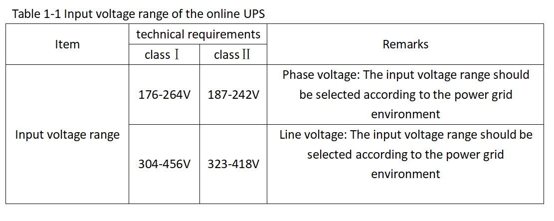
(2)Input frequency range
Input frequency range indicates the input AC frequency used by the UPS and the allowed change range. In mainland China, the standard value is 50Hz, and the input frequency range is 50Hz±1Hz, 50Hz±2Hz, 50Hz±3Hz, etc., which represents the synchronization range of the UPS internal synchronous phase-locked circuit. That is, when the grid frequency is within the range of change, the output of the UPS inverter is synchronized with the grid. When the frequency exceeds the range, the output of the inverter is not synchronized with the grid. The output frequency is determined by the 50Hz sine wave generator inside the UPS. The input frequency of the communication UPS ranges from 48-52Hz.(3)Input power factor and harmonic component of input current
In circuit principle, the power factor of linear circuit is usually expressed by cosφ, where φ is the angle of difference between sinusoidal voltage and sinusoidal current. For nonlinear circuits, although the input voltage is sine wave, the current may be non-sine wave, so the current distortion must be considered for nonlinear circuits. Generally defined asPF=P/S
Where, PF is the power factor; P is active power; S is apparent power. In nonlinear circuits, if the ratio of fundamental wave current effective value to non-sinusoidal current effective value is defined as distortion factor, the current distortion factor D is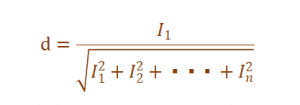 Where, +… , represents 1,2… ,n times harmonic current effective value. If the phase difference between fundamental wave current and voltage is also assumed to be φ, the power factor PF can be expressed as:
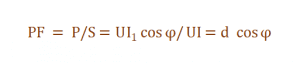 That is, the power factor of nonlinear circuit is the product of distortion factor and displacement factor (cosφ).The input power factor refers to the input power factor and the input current quality of the rectifier charger in the UPS.
It indicates the capability of the power supply to absorb active power from the power grid and the interference to the power grid.
The higher the input power factor is, the smaller the harmonic component content of the input current is, which indicates that the power supply has less pollution to the power grid.
That is, the power factor of nonlinear circuit is the product of distortion factor and displacement factor (cosφ).The input power factor refers to the input power factor and the input current quality of the rectifier charger in the UPS.
It indicates the capability of the power supply to absorb active power from the power grid and the interference to the power grid.
The higher the input power factor is, the smaller the harmonic component content of the input current is, which indicates that the power supply has less pollution to the power grid.
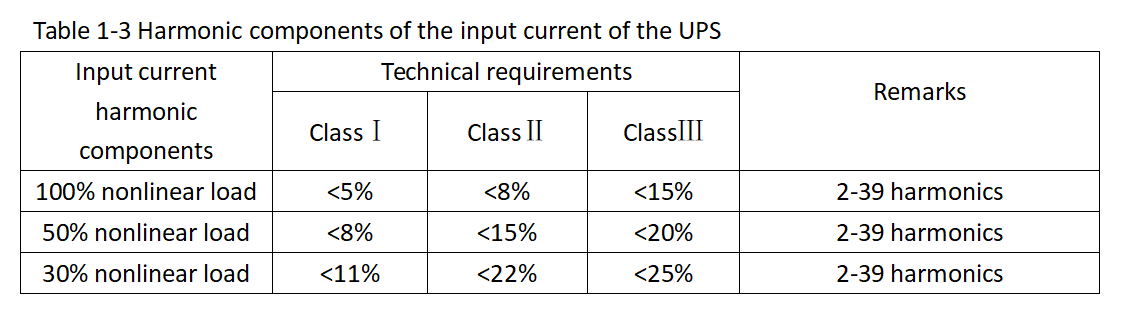
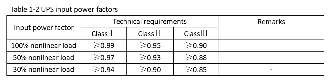 The input power factor of the online UPS meets the requirements of Table 1-2. And the harmonic components of the input current meet the requirements of Table 1-3.
2.Output Indicators
(1)Output voltage
① Nominal output voltage value: single-phase input single-phase output UPS or three-phase input single-phase output UPS is 220V; three-phase input three-phase output UPS is 380V, using three-phase three-wire system or three-phase four-wire system output mode. You can select a UPS and related UPS battery based on the voltage level and power supply system required by your device. ② Output voltage (precision/range) : refers to the output voltage change caused by input voltage change, load change, and temperature change during steady operation of the UPS. For backup and interactive UPS, the output voltage (accuracy/range) should be in the range of 198-242V. For the online UPS, the output voltage accuracy must meet the requirements of Table 1-4. ③ Dynamic voltage transient range: refers to the fluctuation value of the output voltage when the UPS is loading and unloading at 100% or when the grid bypass power supply channel is converted to the inverter power supply channel. UPS dynamic voltage transient range ≤5%.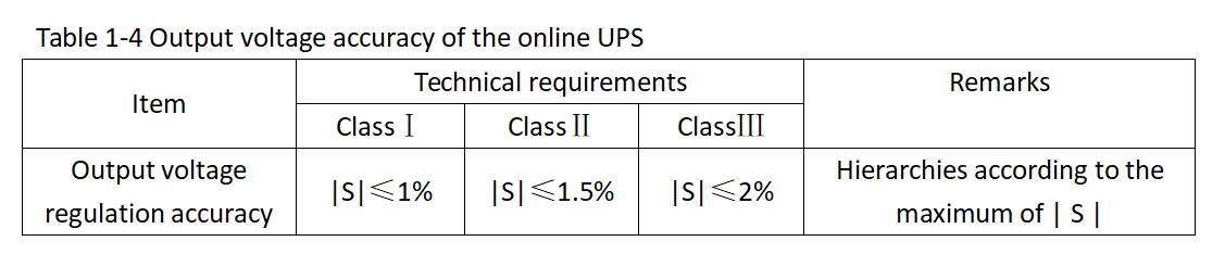 ④ Transient voltage recovery time:
the time required for the output voltage to recover to (224±4.4) V when the input voltage is rated, the output current is resistive load, and the output current changes from zero to rated current or the rated current changes to zero.
The voltage transient recovery time of the backup and interactive UPS should be less than or equal to 60 Ms. The voltage transient recovery time of the online UPS should meet the requirements listed in Table 1-5.
④ Transient voltage recovery time:
the time required for the output voltage to recover to (224±4.4) V when the input voltage is rated, the output current is resistive load, and the output current changes from zero to rated current or the rated current changes to zero.
The voltage transient recovery time of the backup and interactive UPS should be less than or equal to 60 Ms. The voltage transient recovery time of the online UPS should meet the requirements listed in Table 1-5.
 ⑤ Output voltage frequency:
Range of frequency synchro refers to the range in which the UPS output frequency tracks the change of the input frequency during AC power supply.
The frequency tracking range of the UPS ranges from 48 Hz to 52Hz. The rate of frequency synchro indicates the rate at which the UPS output frequency tracks the input frequency if the UPS output frequency is different from the input AC frequency.
The rate is expressed in Hz/s. The UPS frequency tracking rate ranges from 0.5 – 2Hz/s. When working in the output state of the inverter, the ratio (stability) should not be wider than (50±0.5) Hz.
⑥ Output (voltage) waveform and distortion:
according to different uses, the output voltage is not necessarily sine wave, it can also be square wave or trapezoidal wave.
The output waveform of the backup UPS is usually square wave, and that of the online UPS is usually sine wave.
Waveform distortion is generally for the sinusoidal output UPS, refers to the ratio of the square root of the harmonic value of the output voltage to the fundamental wave value. Table 1-6 lists the technical requirements for waveform distortion of the UPS output.
⑤ Output voltage frequency:
Range of frequency synchro refers to the range in which the UPS output frequency tracks the change of the input frequency during AC power supply.
The frequency tracking range of the UPS ranges from 48 Hz to 52Hz. The rate of frequency synchro indicates the rate at which the UPS output frequency tracks the input frequency if the UPS output frequency is different from the input AC frequency.
The rate is expressed in Hz/s. The UPS frequency tracking rate ranges from 0.5 – 2Hz/s. When working in the output state of the inverter, the ratio (stability) should not be wider than (50±0.5) Hz.
⑥ Output (voltage) waveform and distortion:
according to different uses, the output voltage is not necessarily sine wave, it can also be square wave or trapezoidal wave.
The output waveform of the backup UPS is usually square wave, and that of the online UPS is usually sine wave.
Waveform distortion is generally for the sinusoidal output UPS, refers to the ratio of the square root of the harmonic value of the output voltage to the fundamental wave value. Table 1-6 lists the technical requirements for waveform distortion of the UPS output.
 ⑦ Output voltage unbalance (three phase unbalance) :
the three-phase output UPS voltage is different in amplitude, phase difference is not 120 degrees or both.
The amplitude imbalance of the output voltage of the interactive UPS is less than or equal to 3%, and the phase deviation is less than or equal to 2°. The amplitude unbalance of the output voltage of the online UPS is less than 3%, and the phase deviation is less than or equal to 1°.
⑦ Output voltage unbalance (three phase unbalance) :
the three-phase output UPS voltage is different in amplitude, phase difference is not 120 degrees or both.
The amplitude imbalance of the output voltage of the interactive UPS is less than or equal to 3%, and the phase deviation is less than or equal to 2°. The amplitude unbalance of the output voltage of the online UPS is less than 3%, and the phase deviation is less than or equal to 1°.
(2)Output capacity
Capacity is the primary indicator of the UPS, including the input capacity and output capacity. The output capacity is the product of the effective value of the output voltage and the effective value of the maximum output current, also known as the apparent power. The unit of capacity is generally expressed by volt ampere (V·A), which is because the nature of UPS load is different from equipment, so it has to use apparent power to express capacity. Manufacturers divide their products into multiple categories according to different capacity levels of UPS. Users can select the UPS and related UPS battery according to actual needs and leave a certain margin.(3)Output overload capacity
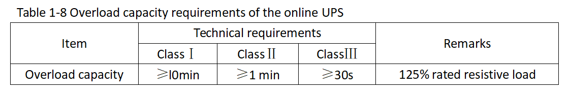
When a UPS starts to load device, transient overload occurs. Output overload capacity indicates the capacity and duration of the UPS to withstand transient overload. The UPS may be damaged if the overload capacity or overload time exceeds the allowed capacity. The overload capacity of the backup and interactive UPS meets the requirements in Table 1-7, and that of the online UPS meets the requirements in Table 1-8.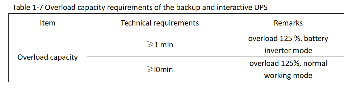
(4)Output current peak coefficient
Peak output current coefficient refers to the ratio of the peak value of the periodic non-sine wave current to its effective value when the UPS output current is periodic non-sine wave current. The peak output current coefficient of the UPS is greater than or equal to 3.(5)Parallel load current unbalance degree
Parallel load current unbalance refers to the ratio of the maximum deviation between the current value and the average current value of the parallel UPS output terminals to the average current value when two or more parallel UPS output terminals supply power in parallel. The parallel UPS load current imbalance should be less than or equal to 5%. The smaller the value is, the better the balance of load current output by each UPS in the parallel system is.3.UPS Battery Indicators
(1)Rated voltage of the UPS battery
The rated voltage of the UPS battery varies with the output capacity. The rated voltage of the UPS battery with a large capacity is higher than that of the UPS with a small capacity. The voltage of the communication UPS battery is 48V. The voltage of some large and medium-sized UPS battery is 72V, 168V, or 220V. The numerical value provides a basis for extending the standby time of additional batteries, and on the other hand provides convenience for the replacement of UPS battery in the future.
(2)The backup time of the UPS battery
This parameter refers to the duration during which the UPS can continue to supply power to loads when the battery strings are in full charge and the battery strings are used to supply power during a grid power failure. Generally, when this indicator is given in the UPS manual, the backup time of full load is given, and sometimes the backup time of half load is also given. Users can arrange the UPS working time based on this indicator and save files before the UPS shuts down. The user should note that the index varies with the state of charge and the degree of old and new of UPS battery.(3)The types of UPS battery
The UPS battery types described in specifications describe the battery types used by the UPS. Users can refer to this instruction when using or maintaining or extending backup time. UPS mostly uses UPS lithium battery, on the one hand, because the performance of lithium ion UPS battery are greater than valve-controlled sealed lead-acid UPS battery. On the other hand, because the cost-effective of lithium ion UPS battery is relatively high. In fact, At present, Lithium Battery Replacement Lead Acid is a new trend in the battery flied, it is no exception for UPS battery.
(4)The charging current limiting range of UPS battery
Avoid damage to the UPS battery due to excessive charging current. The typical value is 10% to 25% of the nominal input current.4.Other Indicators
(1)Efficiency and active power
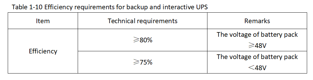
Efficiency is a key indicators of UPS, especially large capacity UPS. It refers to the ratio of the output active power to the input active power under different loads. Generally speaking, the higher the nominal power output of the UPS, the higher the system efficiency.The efficiency of the online UPS meets the requirements listed in Table 1-9.The efficiency of the backup and interactive UPS meets the requirements listed in Table 1-10.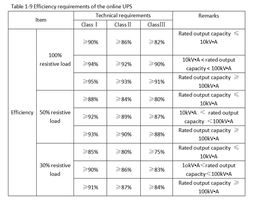
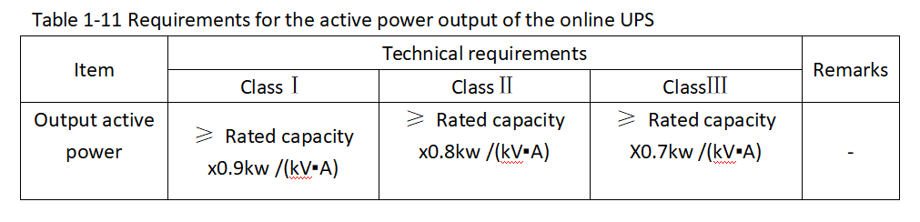
 Backup and interactive UPS output active power ≥ rated capacity 0.74kW/ (kV·A); The active power output of the online UPS meets the requirements listed in Table 1-11.
(2)Conversion time between different operating states
① Grid/UPS battery conversion time. For the online UPS, the grid/UPS battery conversion time should be 0. For backup and interactive UPS, the grid/UPS battery conversion time should be no more than 10ms. ② Bypass/inverter conversion time. For an online UPS, the bypass/inverter conversion time meets the requirements listed in Table 1-12.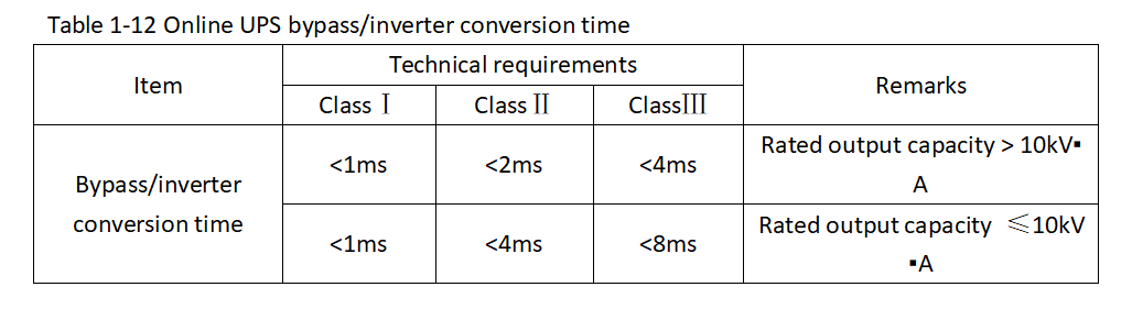 ③ ECO mode conversion time.
When ECO mode is used, the conversion time between ECO mode and other modes meets the requirements listed in Table 1-13.
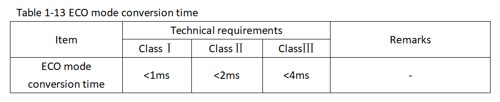
③ ECO mode conversion time.
When ECO mode is used, the conversion time between ECO mode and other modes meets the requirements listed in Table 1-13.
(3)Reliability requirements(mean time between failures, MTBF)
It refers to the time between two consecutive UPS faults calculated by statistical method. It is a measure of UPS reliability. The MTBF of the online UPS should not be less than 10000h (without UPS battery) under normal operating conditions. MTBF of interactive and backup UPS should not be less than 20000 (without UPS battery) under normal operating conditions.(4)Vibration and impact
Vibration: amplitude 0.35mm, frequency 10~50Hz (sinusoidal frequency sweep), 5 consecutive cycles in 3 directions. Impact: peak acceleration 150m/s2, duration 11ms, 3 consecutive impact in 3 directions. UPS with capacity ≥20kV·A can be replaced by transport test.(5)Audio noise
The UPS output is connected to the rated resistive load, and is measured with a sound level meter 1m in front of the UPS at a height of 1/2. The noise is called the UPS audio noise. The audio noise of the backup and interactive UPS must be less than 55dB (A). The audio noise of the online UPS must meet the requirements listed in table 1-14.(6)Remote control and remote message function
①Communication interface. The UPS provides RS485, RS232, RS422, Ethernet, or USB communication ports(at least one of these interfaces). The UPS also provides communication cables and alarm signal output terminals for the ports. ② Remote measuring. UPS telemetry contents are as follows: a. Online and interactive UPS, AC input voltage, DC input voltage, output voltage, output current, output frequency, output power factor (optional), charging current, battery temperature (optional); b. Backup UPS, output voltage, output current, output frequency, battery voltage. ③Remote communication. UPS teleconferencing contents are as follows: a. Online UPS, synchronous/asynchronous, UPS bypass power supply, overload, battery discharge low voltage, grid failure, rectifier failure, inverter failure, bypass failure, and operation status records; B. Interactive and backup UPS, AC/UPS battery inverter power supply, overload, battery discharge low voltage, inverter or converter failure. ④Intelligent UPS battery pack management (online UPS). The UPS with a capacity greater than 20kV·A should provide the automatic floating charge and equalized charge conversion functions for UPS battery pack periodically, automatic temperature compensation for UPS battery pack, and discharge recording functions for battery pack. UPS battery maintenance does not affect system output.(7)Protection and alarm functions
① Output short-circuit protection. When the load is short-circuited, the UPS automatically shuts off the output and generates an audible and visual alarm. ② Output overload protection. When the output load exceeds the rated power of the UPS, an audible and visual alarm is generated. When the overload capacity is exceeded, the online UPS should be transferred to bypass mode. The backup and interactive UPS should automatically shut off the output. ③ Overheat (/ temperature) protection. An audible and visual alarm is generated when the UPS operating temperature is too high. The online UPS should be transferred to bypass mode. The backup and interactive UPS should automatically shut off the output. ④ UPS battery voltage low protection. When the UPS works in battery inverter mode and the battery voltage reaches the protection point, an audible and visual alarm is generated, and the power supply stops.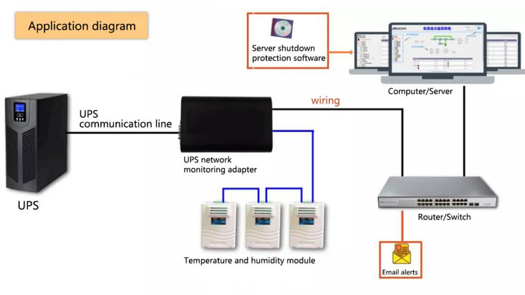 ⑤ Output over-voltage and under-voltage protection.
When the UPS output voltage exceeds the overvoltage threshold or is lower than the undervoltage threshold, an audible and visual alarm is generated.
The online UPS should be transferred to bypass mode. The backup and interactive UPS should automatically shut off the output.
⑥ Fan fault alarm.
When the fan stops working due to a fault, an audible and visual alarm is generated.
⑦ Lightning protection.
The UPS must be able to protect against lightning strikes and voltage surges.
⑧ Maintain the bypass function.
The UPS with a capacity greater than 20kV·A should be equipped with the maintenance bypass function. When the UPS needs to be maintained, the UPS can directly supply power to loads through the maintenance bypass switch.
⑤ Output over-voltage and under-voltage protection.
When the UPS output voltage exceeds the overvoltage threshold or is lower than the undervoltage threshold, an audible and visual alarm is generated.
The online UPS should be transferred to bypass mode. The backup and interactive UPS should automatically shut off the output.
⑥ Fan fault alarm.
When the fan stops working due to a fault, an audible and visual alarm is generated.
⑦ Lightning protection.
The UPS must be able to protect against lightning strikes and voltage surges.
⑧ Maintain the bypass function.
The UPS with a capacity greater than 20kV·A should be equipped with the maintenance bypass function. When the UPS needs to be maintained, the UPS can directly supply power to loads through the maintenance bypass switch.
(8)Electromagnetic compatibility limits
On the one hand, the conducted interference and electromagnetic radiation interference generated by the UPS should be less than a certain limit. On the other hand, it requires the UPS to resist external interference. ① Limit of conducted disturbance.
In the 150kHz-30MHz frequency band, the conducted interference level on the AC input power line of the system should meet the requirements of 8.1 in YD/T983-2018.
② Limit of radiation disturbance.
In the 30-1000MHz frequency band, the electromagnetic radiation interference voltage level of the system should meet the requirements of 8.2 in YD/T983-2018.
③ Disturbance resistance requirements.
The anti-disturbance of the shell surface of the system includes: anti-disturbance of electrostatic discharge and anti-disturbance of radiated electromagnetic field. The system should comply with the requirements of 9.1.1 in YD/T993-2018 during or after the above anti-disturbance tests.
The anti-disturbance of AC port of the system includes: anti-disturbance of electric fast transient pulse group, anti-disturbance of conduction induced by rf field, anti-disturbance of voltage sag and short-time interruption, anti-disturbance of surge (impact).
The system shall comply with the requirements of 9.1.4 in YD/T983-2018 during or after the above anti-disturbance tests: The DC port of the system has the following immunity: the immunity of electric fast transient pulse group and the immunity of conduction disturbance induced by rf field.
The system shall comply with the requirements of 9.1.5 in YD/T983-2018 during or after the above immunity tests.
① Limit of conducted disturbance.
In the 150kHz-30MHz frequency band, the conducted interference level on the AC input power line of the system should meet the requirements of 8.1 in YD/T983-2018.
② Limit of radiation disturbance.
In the 30-1000MHz frequency band, the electromagnetic radiation interference voltage level of the system should meet the requirements of 8.2 in YD/T983-2018.
③ Disturbance resistance requirements.
The anti-disturbance of the shell surface of the system includes: anti-disturbance of electrostatic discharge and anti-disturbance of radiated electromagnetic field. The system should comply with the requirements of 9.1.1 in YD/T993-2018 during or after the above anti-disturbance tests.
The anti-disturbance of AC port of the system includes: anti-disturbance of electric fast transient pulse group, anti-disturbance of conduction induced by rf field, anti-disturbance of voltage sag and short-time interruption, anti-disturbance of surge (impact).
The system shall comply with the requirements of 9.1.4 in YD/T983-2018 during or after the above anti-disturbance tests: The DC port of the system has the following immunity: the immunity of electric fast transient pulse group and the immunity of conduction disturbance induced by rf field.
The system shall comply with the requirements of 9.1.5 in YD/T983-2018 during or after the above immunity tests.
(9)Safety requirements
① Shell protection requirements. The ground screw between the UPS protection ground device and the metal shell must have reliable electrical connection with a resistance less than 0.1 ohm. ② Insulation resistance. The input and output terminals of the UPS apply 500V DC voltage to the shell, and the insulation resistance should be greater than 2M ohm. The positive and negative terminals of the UPS battery apply 500V DC voltage to the shell, and the insulation resistance must be greater than 2M ohm. ③ Insulation strength. The input and output terminals of the UPS apply a 50Hz and 200V AC voltage to the ground for 1 minute. Ensure that there is no breakdown or arc, and the leakage current is less than 10mA. Or 2820V DC voltage for 1min, no breakdown, no arc, leakage current less than 1mA. ④ Contact current and protection conductor current. The contact current between the protective ground (PE) of the UPS and the input neutral line (N) should not be greater than 3.5mA. When the contact current is greater than 3.5mA, the effective value of the protective conductor current should not exceed 5% of the input current of each phase. If the load is not balanced, the maximum value of the three phase current should be used to calculate. And the cross-sectional area of the protective conductor should not be smaller than 1.0mm2 in the large current of the protective conductor; A sign with warning or similar words, “Large contact current, must be grounded before switching on power supply”, should be installed near the primary power supply connector of the equipment.