Up to now, UPS has included many modern advanced electronic technologies in technology, and its application field covers all walks of life in the national economy and plays an extremely important role. Because UPS is technology-intensive and has a prominent position, on the one hand, we should understand and master its principles and technologies as much as possible, and on the other hand, we must be familiar with its operating procedures and maintenance management methods during installation, use and maintenance to achieve safe and reasonable use. UPS and prolong its service life.
Selection of UPS
Factors to consider when choosing UPS
When selecting a UPS, users should determine their own selection criteria according to their own requirements and possibilities. Generally speaking, users should consider three factors: the technical performance of the product, maintainability and price.
①When considering the technical performance of the product, general users pay special attention to factors such as output power, output voltage waveform, waveform distortion coefficient, output voltage stability, and the length of time the battery can supply power. However, the transient response characteristics of a product’s output voltage are often overlooked. Because, as far as the current level of electronic technology is concerned, it is not a problem to ensure the static stability of the UPS AC output voltage.
But for some UPS varieties, the voltage output transient response characteristics are very poor, This is mainly manifested in: when the load suddenly increases or decreases, the output voltage of the UPS fluctuates greatly. When the load changes suddenly, some UPS cannot work normally at all. In addition to the transient response characteristics of the UPS, the user should also pay attention to the performance parameters such as the load characteristics of the UPS and the ability to withstand instantaneous overload. It should be specially pointed out that the UPS with quasi-square wave output cannot carry any load with a leading power factor.
②Users should also pay attention to the maintainability of the product when purchasing UPS. This requires users to pay attention to whether the UPS has a complete automatic protection system and a charging circuit with excellent performance when purchasing a UPS. A perfect protection system is the basis for the UPS to run with money, and a charging road with excellent performance is an important guarantee for improving the service life of the UPS required battery and the actual available capacity of the guarantor battery as close to the product rating as possible.
It should be pointed out that, as far as the UPS is concerned, the cost of the battery is generally about 1/4~1/3 of the cost of the entire UPS. When there is a long delay function and an additional battery cabinet is required, its price can be comparable to the UPS host, or even higher. Therefore, the selection and use of batteries is also an important factor for users to make test products.
③Price is a very important factor for users to consider when choosing a UPS, but when comparing product prices, users should not just look at the price of products on the surface. Due to the current total production cost of UPS, the proportion of batteries is quite high. Therefore, when comparing product prices, we must pay attention to the capacity of the battery equipped with the UPS.
The more objective and scientific comparison method is to look at the two technical performance indicators of the battery: a. The performance-price ratio of the battery, that is, how much does the UPS equipped with the battery cost per Ah capacity on average; b. The discharge efficiency of the battery Ratio, that is, how long the battery equipped with the UPS can keep the UPS working per Ah on average. Obviously, the longer the maintenance time, the higher the utilization efficiency of the battery. Of course, special attention should be paid to what type of battery (including the manufacturer) is configured in the UPS machine.
Influence of load capacity and load power factor on model selection
When purchasing a UPS, you must first know the total capacity of the load, and at the same time consider the power factor of the load to determine the rated capacity of the UPS. The rated capacity of the UPS is generally determined by considering the load power factor of 0.8. In UPS users, more than 80% are computer loads, and most of the power supplies inside the computer use switching power supplies. The average value of the product of the value and the instantaneous current value. Therefore, the instantaneous power (peak power) is very high, but the average actual power is very small. Therefore, the power factor of the general UPS can only reach about 0.65 when the switching power supply is used as the load, while the various UPS load power factor indicators on the market are 0.8. , If the UPS purchased according to this indicator drives the switching power supply load, it will inevitably cause damage to the UPS.
Therefore, when choosing UPS capacity, be sure to consider the power factor (or current crest factor). Since the load power factor is difficult to calculate, the UPS is required to have a current crest factor index in the UPS technical specification. The higher the current crest factor, the stronger the UPS’s ability to withstand nonlinear loads. Generally, the current crest factor ratio should be above 3:1.
Influence of battery backup time on model selection
Valve-regulated lead-acid batteries are widely used batteries in small and medium-sized UPS. According to relevant statistics, the proportion of UPS not working normally due to battery failure accounts for more than 40%. Therefore, when choosing a UPS, you must know the situation of the batteries inside the UPS, such as full-load working time, half working time, battery voltage, capacity, manufacturer, service life, and quality assurance.
Under normal circumstances, when choosing the battery backup time, the full load working time is usually 10min, 15min or 30min. The long-delay UPS is generally only selected in some special occasions where the power outage time is long due to the high price of large-capacity batteries. It can supply power for a long time after the mains power outage.
Influence of centralized power supply and decentralized power supply on model selection
If there are multiple computers that need UPS, should one high-power UPS be used for centralized power supply, or should it be distributed by multiple low-power UPS? If the load is relatively concentrated, in order to facilitate management, a high-power UPS is generally used for centralized power supply.
if the reliability is to be increased, two high-power UPSs of the same capacity can be considered for redundant parallel power supply. Of course, the cost will also increase accordingly; if the load is relatively scattered , and each load is relatively independent, which requires high power supply quality and non-interference with each other. At this time, it can be considered to use multiple low-power UPS to distribute power supply, and the cost is relatively low.
UPS installation
UPS installation conditions
①UPS installation site and environment. For the selection of site and environment, it is necessary to consider both the safe operation of the UPS and the actual situation of the load to ensure that the UPS operates normally and the power supply is reliable. Generally, when considering the UPS installation site and environment, pay attention to the following aspects.
1.The site should be clean and dry. There should be at least 50mm of space on the left and right sides of the UPS, and at least 100mm of space at the back to ensure that the UPS is well ventilated and the humidity and temperature are suitable (15~25°C is the best).
2.No harmful gas (especially H2S, SO2, Cl2 and gas, etc.), because these gases are highly corrosive to equipment components and affect the service life of UPS, and coastal areas should also prevent sea breeze (water) erosion.
3.External battery cabinets should be co-located with the UPS as much as possible.
②The connection between the UPS and the mains power supply and load
1.Check whether the input parameters marked on the UPS power supply are consistent with the voltage and frequency of the mains.
2.Check whether the phase line and neutral line of the UPS input line comply with the manufacturer’s regulations.
3.Check whether the load power is less than the rated power of the UPS.
③Cable cross section selection. UPS is generally installed indoors, and it is close to the load, and its wiring is mostly trenches or wiring troughs, so copper core rubber insulated cables are generally used. The cross-sectional area of the wire mainly considers three factors:
1.Comply with cable safety standards;
2.Comply with the allowable temperature rise of the cable;
3.meet the voltage drop requirements.
The maximum voltage drop required by UPS is: AC 50Hz loop ≤ 3%; AC 400Hz loop ≤ 2%, DC loop ≤ 1%, if the voltage drop exceeds the above range, the cross-sectional area of the wire must be enlarged. The calculation method is as follows:
Find the current value first.
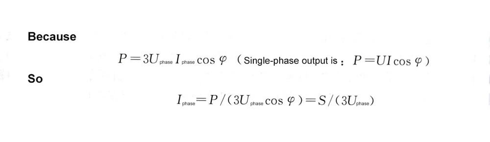
For example, the output current of 380V, 50Hz, 250kV·A UPS is:
Check table 7-1 to determine the wire cross section: when the output line is about 100m long, you can choose a 185mm2 copper core cable, and when it is more than 100m long, it needs to be thicker, because the line voltage drop of 100m can reach 2.7%. If the output line is below 80m, 150mm2 copper core cable can be selected, and the voltage drop is 3.1×80/100=2.48%
Similarly, the minimum cross-sectional area of the battery output line can be determined.
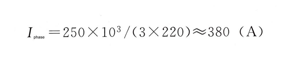
The DC output current I=P/U, it should be noted here that U should take the minimum value.
For 3-phase 380V, 250kV·A UPS with inverter input voltage of 362~480V, the maximum discharge current of the battery is:

Therefore, the battery output line should choose a copper core wire of more than 300mm2.
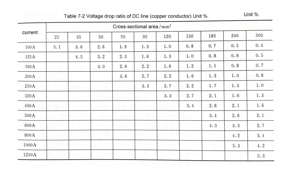
The voltage drop ratio of the 100mm long loop (copper core cable) is shown in Table 7-1 and Table 7-2 for reference when selecting.


UPS installation requirements and precautions
Before the UPS is installed, the UPS supplier will provide the user with complete and detailed UPS installation requirements and precautions. Only when these requirements are met, the UPS will work normally after it is connected to the user’s power supply system.
Here, the installation requirements and precautions of UPS are sorted out according to the different types of UPS input and output. In practical applications, engineers and technicians can fill in the relevant parameters into the blanks and send them to the user according to the actual situation, so that the user can construct according to this requirement (with Single-phase UPS for example).
①The UPS power supply is required to be a single-phase three-wire system (zero, fire, ground), the fluctuation range of the mains power is within 220V±%, and the zero-ground voltage is less than V.
②The circuit breaker with leakage protection cannot be installed in the front stage of the UPS and the load circuit.
③The input neutral line of the UPS cannot be connected to a circuit breaker or insurance (if the neutral line needs to be disconnected, the zero-fire double-break is required).
④The UPS input neutral line and output neutral line (ie, UPS load neutral line) should be separated and cannot be connected together.
⑤ The UPS input live line cannot be connected to the lower port of the circuit breaker with the live lines of other electrical equipment.
⑥ Input rated voltage V, rated current A, breaking capacity kA; output circuit breaker rated voltage V, rated current A, breaking capacity kA.
⑦ Input zero, live wire with mm2, output zero, live wire with mm2, ground wire with mm2 multi-strand copper flexible wire.
⑧If the user is equipped with a long-delay battery outside the UPS (it is recommended that the user place the battery side by side with the UPS host), the length of the connection between the battery and the host should not exceed m.
⑨ It is recommended that the user’s load distribution adopts a hierarchical multi-channel control method, and the total rated capacity of the circuit breaker at the next level should not be greater than 130% of the previous level.
⑩ It is recommended that users set up separate switchboards for the UPS and its loads, and the protection level should reach IP30.
⑪The UPS load socket should be distinguished from other non-UPS load sockets.
⑫ The zero and live wires of the UPS load socket cannot be reversed (left zero, right fire, and ground wire above).
⑬ It is recommended that the UPS and battery work in a dry environment with a temperature between 20°C and 25°C.
⑭The load-bearing capacity of the floor shall not be less than kg/m2, and the installation area shall not be less than m2.
①The input mains fluctuation value provided by the user for the UPS is generally smaller than the nominal allowable mains fluctuation range of the UPS. For example, a certain type of UPS nominally allows the mains input voltage to fluctuate within 220V±20%, and the user can be required to have a mains fluctuation of ±20%. 15%, which is conducive to the normal operation of the UPS; the neutral-to-ground voltage is generally required to be less than 1.5V without load and less than 2V with full load. Engineers and technicians can also propose this value according to site conditions and load requirements.
②In order to eliminate common mode interference, UPS usually adds filter capacitors between the zero and live lines to the ground, which may cause the currents on the zero and live lines to be unequal, thereby tripping the circuit breaker with leakage protection. Therefore, the UPS front stage and load circuit cannot be equipped with a circuit breaker with leakage protection, so as to avoid accidental power failure of the UPS and its load. It should be pointed out here that the main purpose of installing a UPS by users is to ensure the safe operation of important loads (such as computers), and at the same time to ensure the safety of personnel. combine.
③From the perspective of safe electricity use, the neutral line (especially the neutral line in the trunk line) cannot be disconnected. Even if it is to be broken, the neutral line and the live line should be disconnected at the same time.
④In order to eliminate electromagnetic interference, the input neutral line and output neutral line of most UPS are isolated or go through a choke coil, so the neutral line of UPS output (that is, the load) cannot be connected to the input distribution when doing UPS power distribution. on the neutral busbar. The user can connect the UPS output (load) neutral line to a single neutral line. However, some brands of UPS have a direct connection between the input and output neutral lines, so that the input neutral line and the output (load) neutral line can be connected to the same busbar.
⑤ The UPS input circuit breaker is specially used to control the on-off of the UPS input power, so the lower port of the UPS input circuit breaker should not be connected to other electrical equipment, so as not to affect the normal on-off of the UPS input power.
Here is a point to explain, some users require the UPS to work on battery backup for a long time after the mains power fails. In this way, the capacity of the external long-delay battery equipped with the UPS is very large. In order to ensure that the external battery has sufficient charge Current (usually 10% of the total battery capacity), the manufacturer will equip the UPS with an additional battery charger. The AC input power of the charger must be turned on and off at the same time as the input power of the UPS to ensure charging when there is commercial power. The external battery is charged by the charger. When the mains power is cut off, the battery is immediately discharged to the UPS inverter through the charger. Therefore, the AC input of this charger should be connected to the lower port of the same circuit breaker as the input power of the UPS.
⑥When selecting input and output circuit breakers for UPS, firstly, the nominal rated voltage of the circuit breaker is required to conform to the rated input and output voltage of the UPS. It is a 220V or 250V circuit breaker, and the three-in, three-out UPS can choose a three-pole (or N+3, or four-pole) circuit breaker with a rated voltage of 380V or 415V. It should be noted that the rated breaking capacity ICU of the circuit breaker must meet the requirements of the UPS manufacturer. Generally, the rated breaking capacity of the small UPS circuit breaker is 10kA or 6kA, and the large and medium UPS are required to be above 30kA.
The nominal rated current of the circuit breaker is greater than the maximum input current and output current of the UPS. Generally, the UPS manufacturer will directly give the rated working current value of the input and output circuit breakers or the maximum input and output current value of the UPS. It can also be calculated by the following formula:

In the formula, Iinmax is the maximum input current, A; P is the nominal capacity of the UPS, V·A; PFout is the load power factor; PC is the charging power: W, if the PC value is not given by the manufacturer, it can be calculated by the formula PC≈UCIC where UC is the equalizing voltage of the UPS, V; IC is the equalizing current (or maximum charging current) of the UPS, A; The ratio of active power to input precision power), which is a constant; PFin is the input power factor; Uinmin is the minimum commercial power input voltage given by the manufacturer when the UPS is working at full load (without battery power supply); Ioutmax is the maximum output current of the UPS , A; Uoutmin is the minimum output voltage of the UPS, V.
Online UPS is regulated output, so Uoutmin can be 220V. For some online interactive UPS, when the mains input voltage is within a certain range (for example, a certain type of UPS is 192~250V), the UPS directly outputs this voltage to the load, only when the mains input exceeds this range, Only after the UPS adjusts the input voltage (such as automatic boosting or bucking by 12%), it outputs to the load, so in this case, the minimum output voltage of the UPS should be the minimum input voltage when the UPS does not adjust.
In addition, many manufacturers will allow the UPS to work with short-term overload (100%~125% of the nominal power of the UPS), and the circuit breaker is also allowed to operate after 1~2min when the overcurrent is 125%, so this kind of overload is generally not allowed. consider.
Example: a certain type of 16kV·A single-input single-output UPS, its input voltage range is 155~276V (full load), the input power factor is 0.98, the load power factor is 0.7, the charging power is 1.2kW, and the overall efficiency is 0.91 at full load, then Its maximum input current Iinmax=(16000×0.7+1200)/(0.91×0.98×155)=89.7(A), and the maximum output current Ioutmax=16000/220=72.7(A). The rated working current of the UPS input and output circuit breakers can be selected from 100A and 80A respectively.
The load carried by the UPS (rectifier load when the computer switches current) is usually inductive, and the power factor is generally 0.6~0.7. Even if a power factor correction circuit is added to the UPS input end, when the UPS bypass works, due to the load, the input The terminal is also inductive, and the starting current of the inductive load is relatively large, so when selecting the input and output open circuit, the tripping curve should be class D (10~20 times the rated current tripping).
Some UPS manufacturers consider that the circuit breaker may malfunction in some cases, resulting in unexpected power outages of input power and output (load) distribution, so they will require the use of load isolation switches or load isolation switches with fuses. When selecting switches and fuses, their rated current should also be greater than the maximum current and maximum output current.
It is particularly worth noting that most of the three-in-one-out UPS models, when switching to bypass operation, all load is borne by one phase of the input three-phase power, so when selecting the input circuit breaker (multi-pole) When the rated working current is not less than the single-phase maximum input current when working at full load.
⑦ For the selection of the UPS input and output wiring diameter, refer to the maximum current passing through each phase. Considering that there may be third harmonic currents on the neutral line in the three-phase equipment, so the three-in-one-out and three-in-three-out zero The wire diameter (especially the output neutral wire of the UPS) should not be smaller than the wire diameter of A-phase (three-in-single-out UPS, A-phase is usually set as bypass power). The diameter of the protective ground wire is also generally required to be the same as that of the A-phase wire.
The connection line of UPS generally uses BVR line, YZ, YC multi-core soft image sleeve line or RVV multi-core soft plastic sleeve line.
Current density (current intensity per mm2 cross-sectional area) can be estimated by the following values: 1.5mm2/8A, 2.5mm2/7A, 4mm2/6.5A, 6mm2/6A, 10mm2/5.5A, 16mm2/5A, 25mm2/ 4A, 35mm2/3.5A, 50mm2/3A, 70mm2/2.5A, no more than 2A above 95mm2.
⑧The connection between the UPS and the external long-delay battery should not be too long, otherwise the voltage drop lost on the battery connection is relatively large. In addition, users often pay great attention to the ambient temperature of the UPS host. Placing the battery together with the host can also provide a good working environment for the battery.
⑨ The user’s load distribution should preferably adopt the hierarchical multi-channel control method. When overcurrent or short-circuit protection occurs in a branch at the end, it will not cause other roads in the same level or the electrical equipment at the upper level to lose power, and the total rated current value of the circuit breaker at the next level should not be greater than that of the previous level. 130%, to avoid that when each branch circuit breaker in the next level is not fully loaded or overloaded (the circuit breaker does not trip), the circuit breaker at the previous level is tripped due to overload, and all loads lose power.
In addition, the tripping curve and tripping time of the circuit breaker at the previous level should be greater than the tripping curve and tripping time of the circuit breaker at the next level, so as to avoid the peak, surge or short circuit in the branch in the next level. The circuit breaker trips before the next-level circuit breaker, causing the entire load to be de-energized.
For a three-in-three-out UPS, the user is required to distribute the three-phase load as evenly as possible, so as to avoid the UPS being transferred to the bypass state due to the overload of one of the three-phase output of the UPS, thereby reducing the protection level of the UPS to the load.
⑩It is recommended that the user set up a separate distribution board for the UPS and its load. In order to facilitate centralized, reliable control of the UPS and the load it protects. The components selected for this switchboard must meet the national flame retardant and insulation requirements.
The first type of protection form: prevent solid foreign objects from entering the interior of the appliance and prevent protection. The classification method and definition of the first type of protection form are shown in Table 7-3.
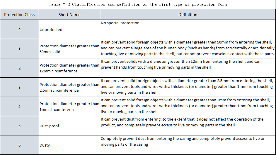
The second type of protection: protection against water entering the interior to a harmful level. The classification method and definition of the second type of protection form are shown in Table 7-4.
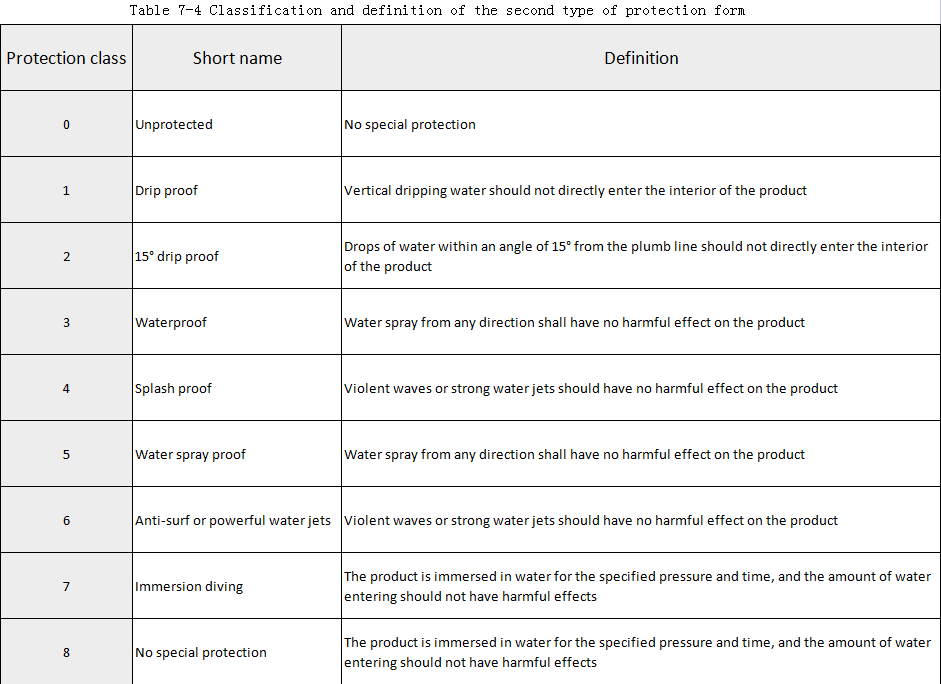
The mark indicating the protection level of the product shell consists of the letters “IP” and two numbers. The first digit represents the level of the above-mentioned first type of protection form, and the second digit represents the grade of the above-mentioned second type of protection form.
When it is necessary to separately mark the level of the first type of protection form, the position of the omitted number should be supplemented with the letter “X”. For example, IP3X means the first type of protection form level 3. The engineers and technicians can install the equipment according to the location, The location and the UPS manufacturer require the proposed degree of protection.
⑪Users all know that air conditioners, lighting and other equipment cannot be connected to the UPS output terminal, but if the user is doing UPS load distribution, there is no obvious distinction between the UPS load socket and the non-UPS load socket, which may cause users to mistakenly The UPS load is inserted into the special socket for UPS load, which affects the normal operation of the UPS. Therefore, special marks that are clearly different from other sockets should be made on the special socket for UPS load.
⑫ For some UPS loads that require single-phase three-wire power supply, inside the equipment, the neutral wire and the protective ground wire are connected together. If the neutral and live wires of the UPS load socket are connected in reverse, it may cause damage to the UPS and the load. Therefore, the user must check the polarity of the zero and live wires of the UPS load socket when distributing the load, and cannot be reversed. For the socket, facing the plug, it is the ground wire, the live wire, and the neutral wire. For the plug, facing the plug, starting from the protective ground wire, in a clockwise order, it is the ground wire, the neutral wire, and the live wire.
⑬ For the UPS external battery, the basic conditions for correct installation and safe operation are as follows:
The working environment of the UPS and battery is dry, and the temperature is between 20°C and 25°C.
The overcurrent protection circuit breaker or fuse must be installed in the charging and discharging circuit of the battery pack, and the closer the protection device is to the battery, the better. Some fuses can even be connected in series in the battery pack, so that when the output line of the battery pack is insulated When damaged or the output is short-circuited, the output voltage of the battery pack can be cut off quickly.
The rated working voltage (DC) of the overcurrent protection circuit breaker or fuse should be greater than the floating charge voltage of the UPS battery bank, because although the voltage difference between the charger and the battery bank is not very large when the UPS is working normally, if the internal or If there is a short circuit between the positive and negative lines of the output terminal of the charger, it is possible that the voltage close to the voltage value of the entire battery pack will be added to the circuit breaker. The working voltage must be greater than the float voltage of the UPS battery pack.
The rated working current of the overcurrent protection circuit breaker or fuse should be greater than the maximum discharge current of the battery pack, the maximum discharge current of the battery connection group, and the calculation formula of the maximum discharge current is as follows:

In the formula, IBatmax is the maximum discharge current of the battery pack, A; P is the nominal capacity of the UPS, VA; PFou is the load power factor; The efficiency of the battery pack DC to the UPS AC output is a constant; UBaot is the battery pack shutdown voltage when the UPS works in the battery inverter, V.
It should be noted that the shutdown voltage value set by some manufacturers during high current discharge is smaller than the shutdown voltage value during low current discharge. For example, a certain type of UPS DC operating voltage is 120V/DC, and when the load is below 50%, the battery shutdown voltage Set to 105V, when the load is above 50%, the battery shutdown voltage is set to 100V.
⑭ Since the UPS host and its batteries are generally heavy, it should be calculated whether the load capacity of the ground reaches the distributed load of the weight of the UPS and its batteries. Requirements for installation area: For UPS below 20kV.A, the work area should not be less than 10~20m2; for 20~60kV.A UPS, the work area should not be less than 20m2; for large UPS above 60kV.A, The working area should not be less than 40m2.
For users who require 24h uninterrupted operation of the UPS, it is very necessary to configure a separate maintenance bypass distribution box for the UPS. Through the correct operation of the UPS and its maintenance bypass distribution box, the user can switch the UPS load to the manual maintenance bypass of the electric box without interruption, and then make the UPS host completely uncharged, and the engineering and technical personnel can safely UPS for repairs.
After the maintenance work is completed, by operating the UPS and the maintenance bypass distribution box, the user can also switch the UPS load from the manual maintenance bypass back to the UPS online output circuit without interruption. The structure and operation method of the maintenance bypass distribution box are shown in Figure 7-1 and Figure 7-2 (take a single-input single-output UPS as an example).
S1 is the UPS input circuit breaker, S2 is the UPS output circuit breaker, and S3 is the UPS maintenance bypass switch.
a. Normal boot sequence (initial state Si, S2, Ss are all OFF)
(a) Turn S1 to ON and start the UPS normally;
(b) After confirming that the UPS output voltage is normal, turn S2 to ON;
(c) Turn on the load, at this time S3 remains in the OFF state.
b. Transfer to maintenance bypass sequence (initial state S1, S2 is ON, S3 is OFF).
(a) Confirm that the mains power supply is normal, and switch the UPS host to the bypass state (internal bypass).
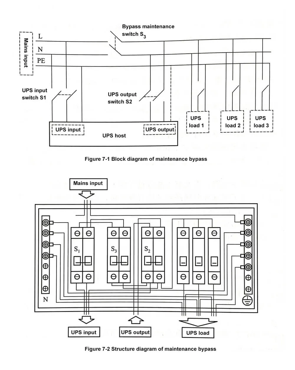
(b) After confirming that the voltage difference between the upper and lower ports of Sa does not exceed 2V, turn Ss to ON.
(c) After confirming that the load is operating normally, turn S2 to OFF.
(d) Turn S1 to OFF. At this time, the UPS equipment has been disconnected from the entire power distribution circuit and can be maintained.
If the UPS cannot be switched to the internal bypass, it is necessary to completely shut down the UPS in the normal sequence, turn S2 to OFF, and turn S1 to OFF, and the load will be turned off at this time; if the load needs to continue to work, confirm that S1 and S2 are OFF. After the state, will be turned ON, and then turn on the load.
c. Return to normal working sequence (initial state S1, S2 are OFF, S3 is ON)
(a) Turn S1 to ON;
(b) Start the UPS and confirm that the UPS enters the bypass state (internal bypass)
(c) After confirming that the voltage difference between the upper and lower ports of S2 does not exceed 2V, turn S2 to ON.
(d) Transfer the UPS from the bypass to the online state, at which time the UPS returns to the normal working state.