One of the future development trends of power supply equipment based on modern power electronic technology is modularization. Modularization not only improves the reliability of the system, is easy to expand, but also is easy to use and maintain, and is convenient for mass production. For UPS, reliability has always been its goal, and parallel redundancy technology is an important support technology to achieve modularity and improve system reliability.
Basic Principles of UPS Parallel Redundancy
The necessity of UPS parallel connection
In a high-power UPS power supply system, when the capacity of the UPS system needs to be increased due to an increase in load, it can be achieved through two paths: ① The design capacity of a single UPS can be increased. ② Using multiple UPSs in parallel to share the load current.
For the first solution, when a single power supply is powered, once a failure occurs, the system may be paralyzed and cause immeasurable losses; UPS power supply parallel technology can well meet the needs of large-capacity occasions.
The so-called parallel redundancy refers to the parallel connection of N+n UPS modules, where N units are used to supply the current required by the load, and n units are the backup redundant modules. When the working module fails, the backup redundant module is put into operation. In this way, even if n of the N modules in operation fail at the same time, the UPS system can guarantee to provide 100% of the load current.
In addition, the use of redundancy technology can also realize the hot replacement of UPS power modules, that is, to replace the failed modules of the system without interruption of the system’s power supply capacity. The superiority of the power supply system composed of parallel redundant UPS power supplies is reflected as follows:
(1) High reliability. The electrical stress of the power semiconductor devices of each module is reduced, and it is easy to form an N+1 redundant power supply system, which improves the reliability of the system.
(2) The capacity of the inverter power supply system can be expanded flexibly to meet the actual needs of users.
(3) Easy to use and maintain. Building block type, intelligent system site maintenance failure unit is convenient and fast, and it is easy to expand system functions.
(4) Reduce product types, facilitate standardization and standardization, and reduce product development cycle.
(5) Parallel system power supply, single module power is small, switching frequency can be very high, thereby increasing the power density of UPS parallel system.
Obviously, UPS parallel redundancy technology can theoretically increase the capacity of the power supply system without limitation, so it has attracted more and more attention and has become a research hot spot of large-capacity UPS power supply systems.
Basic principle of UPS parallel connection
To realize the parallel operation of UPS inverter power supplies, the key is that the inverters of each UPS should share the load current, that is, to realize current sharing control. Take 2 UPS inverter power supplies in parallel as an example for analysis.
The equivalent circuit of two inverter power supplies running in parallel is shown in Figure 4-30. Among them, U1, U2 represent the fundamental wave voltage output by each inverter, L1、L2、C1、C2 represent the output filter of the inverter, and R is the system load.
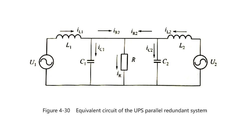
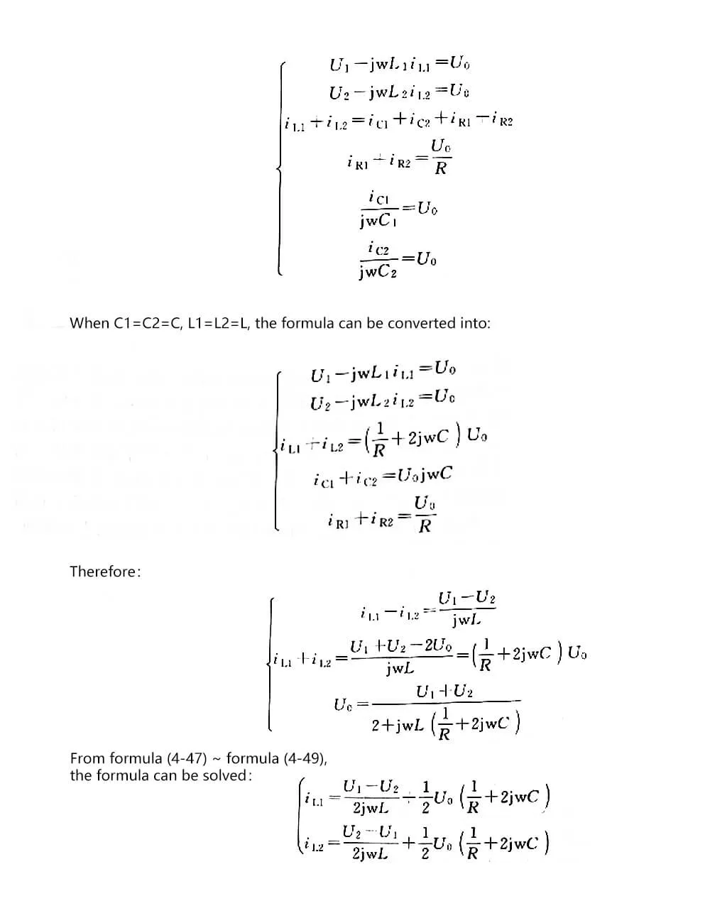
It can be seen from the formula (4-50): iL1 and iL2 are composed of two parts of current, one is the load current component, and the other is the circulating current component. When the output filters are the same, the load current components are always balanced. But the existence of the circulating current component will make the output current of the inverter vary.
When U1 and U2 are in phase, the high-voltage circulating current component is capacitive, and the low-voltage circulating current component is inductive.
When U1 and U2 have the same amplitude, the circulating current component whose phase is advanced is a positive active component and outputs active power; the circulating current component whose phase is lagging is a negative active component and absorbs active power.
Technical requirements for UPS parallel connection
Unlike the DC power supply, the UPS power supply outputs a sine wave. When paralleling, the amplitude and phase angle of the output voltage need to be controlled at the same time, that is, it requires the same frequency, the same phase, and the same amplitude to run. From the analysis of the basic principles of UPS parallel connection above, it can be seen that if the output voltage amplitude or phase of each UPS power supply module is inconsistent, active circulating current and reactive circulating current will be generated between the modules.
In addition, even if the modules have the same frequency, same phase, and same amplitude In operation, if the harmonic content of the respective output voltages is large, there will be a harmonic circulation between the modules. Therefore, the safe parallel operation of inverters needs to meet the following conditions.
(1) Power sharing: The frequency, phase, amplitude, waveform and phase sequence of the output voltage of each inverter module in the parallel system are basically the same. Each module shares the fish-load current equally to balance the output static power and instantaneous power distribution.
(2) Automatic fault diagnosis: When a single module fails, the parallel system can quickly locate the faulty inverter, remove it from the parallel system, and evenly distribute its power to other modules
(3) Hot swap: when the difference in frequency, phase, amplitude and phase sequence between the inverter module to be put into control its output voltage and the parallel system voltage is less than the allowable error, it will automatically put into the parallel system, and the impact on the parallel system will be small when put into operation. ; When any module fails or needs to be overhauled, it can exit the parallel system online without powering off.

The development direction of UPS parallel redundancy
The parallel redundancy of UPS is a current research hotspot. Many scholars and UPS manufacturers have carried out the research of parallel redundancy technology in UPS in the following aspects.
(1) The number of parallel units is quantified and the parallel control methods are diversified. At present, several well-known brands of UPS power supply companies can realize parallel connection but the maximum number of parallel units does not exceed 10. PK Electronics claims that it can connect more than 100 units in parallel.
(2) In the low-power UPS power supply, a more advanced parallel strategy is realized at a lower cost. At present, most of the inverter power supplies that can be connected in parallel are medium and high-power UPS power supplies. Therefore, in order to achieve parallel operation, the increase in the cost of the control circuit will not have a significant impact on the total cost.
The control circuits of ordinary low-power UPS power supplies are generally simpler, and their performance is not as good as that of high-power. Therefore, to realize its parallel operation, the design of the circuit is more difficult. In terms of solving the contradiction between control circuit characteristics and cost, major companies have some unique design methods.
(3) Using a new high-utility power supply system design scheme. The use of a new high-utility power system design scheme can ensure the reliability and flexibility of the entire system. On the one hand, the design of this new type of power supply system should meet the needs of high-power loads and increase a certain amount of redundancy for the power supply system.
On the other hand, it should be based on reliability and can eliminate the impact of any single point failure in the system. Therefore, in the future, most UPS power systems will be based on multi-modular parallel operation current sharing control mode, and use hot-swappable maintenance methods to improve the working performance of the entire system
(4) Using high-frequency chain structure technology. In order to complete the parallel connection of UPS power supplies, improve performance and reduce the volume of modules, most companies adopt high-frequency chain structure technology. The power frequency transformer is reduced in the inverter, the volume and weight of the device are greatly reduced, and the cost is also saved, and the complexity of the device is reduced.
(5) Using a new type of inverter power control technology. The control technology of a single UPS is crucial to its output performance. Previous research on UPS inverter units focused on the use of new power devices to achieve high-frequency switching and SPWM control, reduce the size of the filter, and achieve low output impedance through the optimized design of the filter, thereby suppressing output waveform distortion and The purpose of improving load adaptability.
After the new power switching device technology matures, in order to further improve the dynamic and static characteristics of the inverter, many new control methods have been proposed accordingly, such as: current feedforward control based on instantaneous voltage control, based on variable structure theory Sliding mode control, space-vector control in three-phase inverter power supply system, deadbeat control based on microprocessor, hysteresis current control, etc. These new control methods greatly improve the performance indicators of UPS.
(6) Adopt full digital control technology. In order to improve the control performance of the system and complete the complex algorithm of parallel control, it is best to use a fully digital control scheme for the control of the UPS power supply, such as the use of a single-chip or DSP to complete the detection, operation and control of the system.
Advanced control technology is one of the essential key technologies to improve the efficiency and performance of the converter circuit. However, the use of digital control can avoid the various defects of traditional analog circuit control. Therefore, the development direction of converter circuit control technology is digitization. Digital control makes it easy to implement various complex control algorithms, and further reduces the volume and weight of the equipment, and improves the accuracy and performance.
UPS parallel redundant control strategy
According to the technical requirements of UPS parallel connection, the parallel redundant control mode of UPS system can be divided into four schemes: centralized control, master-slave control distributed logic control and independent control without interconnection lines.
Centralized control method
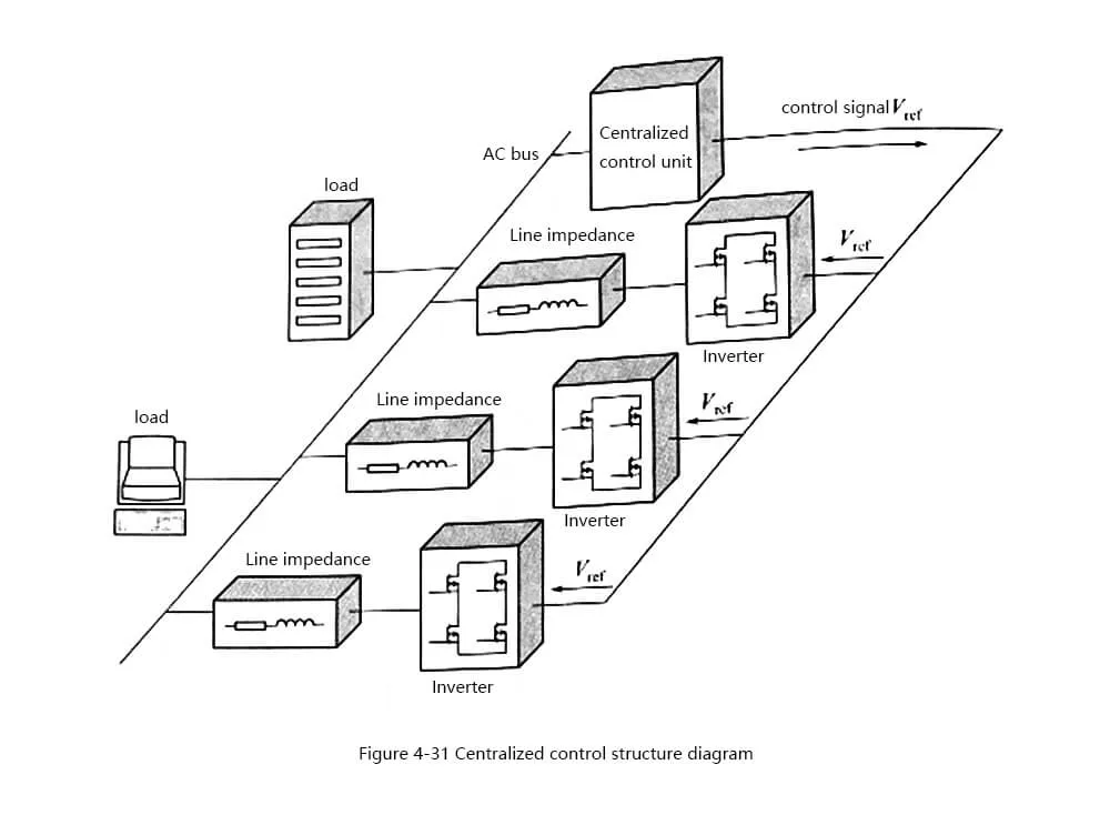
Centralized control is the earliest inverter parallel control strategy. Its structure is shown in Figure 4-31. The parallel system is equipped with a centralized control unit. When the system is running, the centralized control unit first detects the phase and frequency of the mains power, and then synthesizes it. The synchronization pulse signal is sent to each inverter module through the interconnection line between the modules.
The frequency and phase of the synchronization pulse signal are the same as that of the mains, ensuring that the inverter output voltage is consistent with the mains voltage. When the mains power is interrupted, the internal crystal oscillator of the centralized control unit sends out a synchronization signal. Under the control of the synchronous pulse signal, the output voltage phase and frequency difference between the modules is very small.
It is considered that the voltage amplitude difference between the modules is the direct factor that causes the circulating current between the modules. In the control link, the output current of the single inverter module is compared with the system output. The difference of the current is used as the compensation amount of the inverter output voltage, and the parallel current sharing control is realized by changing the output voltage amplitude of the inverter module.
However, for centralized control, a separate centralized control unit must be set up in the system. On the one hand, it is difficult for the parallel system to achieve true modularization; on the other hand, if the control unit fails, the entire inverter parallel system will be paralyzed. Therefore, the centralized control method cannot really achieve the purpose of high reliability and true redundancy, so this method is rarely used in parallel systems at present.
In view of the restriction of the centralized control unit on the reliability of the parallel system, the master-slave control is further proposed. When paralleling, the system sets a certain module as the master and outputs as a voltage source inverter; the other modules in the system are slaves and are output as a current source inverter.
The master uses dual-loop control to ensure the sine of the output voltage waveform; at the same time, the output current signal of the master will serve as the reference signal of the slave, and the slave uses the current loop to track the current reference of the master to ensure that the output currents of the parallel inverter modules are the same. The master-slave control structure is shown in Figure 4-32.
Master-slave control mode
It can be seen from Figure 4-32 that the master-slave control no longer has a separate centralized control unit, and the master module in the system will perform the functions of the control unit. Nevertheless, the core idea of master-slave control is still consistent with centralized control, but the control The power is concentrated in the current main module of the system. When the main module fails, the system will automatically remove the main module and select a new main module from the original slave modules to ensure that the system continues to work normally.
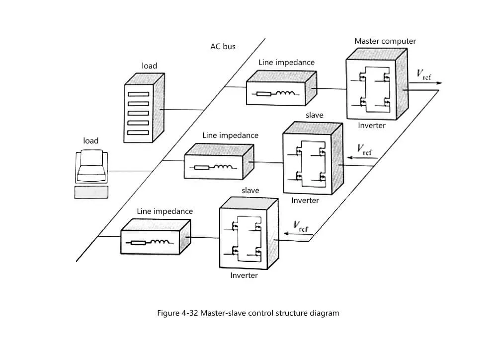
The master-slave control solves the problem of system failure caused by the failure of the control unit in the centralized control, and improves the reliability of the system. However, in the master-slave control, the switching process of the master-slave machine and the control circuit are extremely complicated. When the current master fails to the new master Before the setting is completed, the system will be in an uncontrolled state, so there is a possibility that the switch will fail. Compared with centralized control, master-slave control has improved system reliability, but system out of control may still occur, and the control effect is still not ideal.
Distributed logic control mode
In view of the possibility of system out of control when the master-slave control logic is switched, people propose decentralized logic control, which evenly distributes the control rights to each inverter module, forming a truly democratic and independent control, and system control is no longer dependent on In the master control unit, the parallel modules pass through the communication line and receive the output voltage information of the other modules to realize voltage phase lock, power sharing and logic switching. Figure 4-33 shows the distributed logic control structure.
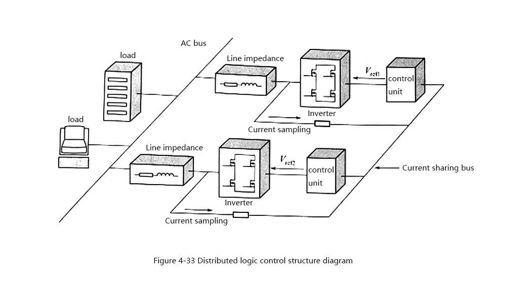
Compared with centralized control and master-slave control, decentralized logic control eliminates the unified centralized control unit. In the parallel system, each module works independently and has the same status. The reliability of the system is greatly improved. The inverter has interconnection line parallel control. The most practical and reliable control strategy in technology is widely used in actual UPS products.
However, for large-scale power supply guarantee systems, there are a large number of parallel modules in the system, and the physical locations are scattered. At this time, too many interconnections will greatly increase the complexity of the inverter parallel system structure and severely restrict the reliability of the parallel system.
No interconnection control method
In order to solve the restriction of the interconnection line between inverter modules on the reliability of the parallel system in the parallel control of inverters with interconnection lines, a series of research and exploration have been carried out on the parallel control technology of inverters without interconnection lines, and certain results have been obtained. Figure 4-34 shows the parallel control structure of inverters without interconnections.
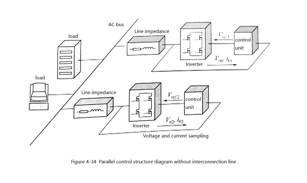
Parallel control without interconnection of inverters can be divided into two types: parallel control without interconnection based on power line communication and parallel control without interconnection based on PQ external characteristic droop. Among them, the parallel control without interconnection based on power line communication uses spread spectrum chip The inverter output voltage and current information is modulated and superimposed on the AC bus.
When the signal is transmitted through the AC bus, each module receives and demodulates the status signals of the remaining inverters in the parallel system, and obtains the control signal of this module after comprehensive calculation Although this method realizes the parallel connection of inverters without interconnections, after high frequency signals are superimposed on the AC bus, the inverter output voltage waveform will be distorted, and the inverter status signal will also be affected by the AC bus voltage. Including the influence of harmonics, therefore, the effect of parallel control without interconnection based on power line communication is not ideal.
Drawing lessons from the droop control principle in the self-synchronization of synchronous generator sets, people proposed a parallel control without interconnection line based on the PQ external characteristic droop. Each parallel module in the parallel system only needs to detect its own output voltage and current signal, and the control unit in the module is used to do The control signal of this module can be calculated to realize current sharing control. The status communication line between parallel modules is eliminated, the electrical isolation between parallel modules is realized, the reliability and stability of the parallel system are improved, and the system configuration is more flexible.
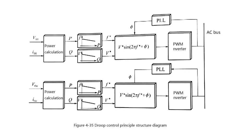
The basic idea of inverter parallel control without interconnection is PQ external characteristic droop control, referred to as droop control. The droop control uses the corresponding relationship between the inverter output voltage phase and amplitude and the output active power and reactive power, and controls the inverter output active power and reactive power by adjusting the inverter output voltage frequency and amplitude. The power then achieves the purpose of parallel current sharing of modules. Figure 4-35 shows the principle of droop control.
Based on the above analysis, the advantages of inverter parallel control without interconnection are:
(1) The status interconnection lines between parallel modules are eliminated, electrical isolation is realized, and the noise between parallel modules is avoided to interfere with the real redundant power supply, which greatly improves the reliability of the system.
(2) Realization of modularization in the true sense, and each inverter module has a hot plug-in function, system maintenance and expansion is extremely convenient.
(3) Due to the “independent self-made” between parallel modules, each module only obtains the control signal through the output voltage and current calculation, so the control system needs to be adjusted in a very short time, which requires high detection accuracy of the system and the command cycle of the control strategy. Otherwise, the droop control effect will be affected.
(4) Because the system adopts droop control, there is a steady-state error between the inverter output voltage frequency and amplitude and the mains, and the external characteristics of the power supply are relatively soft, which is not suitable for loads with strict requirements on voltage amplitude and frequency.
(5) The nature of the inverter output impedance has a great influence on the droop control effect. In the actual system, the influence of the difference between the inverter output impedance and the line impedance on the droop control effect must be considered.