What is AC to DC converter?
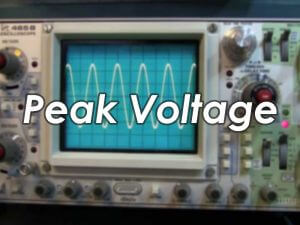
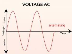
AC is an acronym for Alternating Current. AC is a current that changes periodically in magnitude and polarity (direction) over time. The number of times the current polarity changes in 1 second is called the frequency and is expressed in Hz.
DC is an acronym for Direct Current. DC is a current whose polarity (direction) does not change with time. A current that flows neither in polarity (direction) nor in magnitude over time is often referred to as DC. The flow polarity does not change with time, but the current whose magnitude changes with time is also DC and is often referred to as ripple current. An AC to DC converter refers to a component that converts AC (alternating voltage) into DC (direct voltage).

Why do I need an AC to DC converter?
The voltage received by houses and buildings is AC voltage of 100V or 200V. However, most of the appliances we use operate on a DC voltage of 5V or 3.3V. That is, the appliance cannot work without converting the AC voltage to a DC voltage.
Among them, there are also products that can be driven by AC voltage, such as motors and light bulbs, but the motors are connected with the control circuit of the microcontroller, and the light bulbs also become energy-saving LEDs, so AC to DC conversion is necessary.
Why is the AC voltage being transmitted?
One might think that since appliances use DC, why not transmit DC in the first place? As we all know, electricity comes from hydroelectric power plants, thermal power plants, nuclear power plants, etc. These power stations are located in areas such as mountains or coastal areas, and from these areas to urban areas, AC voltage is more advantageous.
In short, by transmitting AC voltage with high voltage and low current, transmission loss (energy loss) can be reduced. However, in an actual home, since high voltage cannot be used directly, it needs to be transformed (stepped down) through several substations in stages, and finally converted into 100V or 200V and then entered into the home. These conversions are also simpler because of AC, so the AC voltage is transferred.
Rectification methods of AC to DC converter

The rectification methods for converting AC to DC are full-wave rectification and half-wave rectification. In both cases, the forward current flow characteristic of the diode is used for rectification. Full-wave rectification is to convert the negative voltage component of the input voltage into a positive voltage through a diode bridge circuit structure and then rectify it into a DC voltage (pulse voltage).
The half-wave rectification uses a diode to eliminate the input negative voltage component and rectify it into a DC voltage (pulse voltage). Afterwards, the waveform is smoothed by the charging and discharging function of the capacitor, which is converted into a pure DC voltage. Therefore, it can be said that full-wave rectification is a more efficient rectification method than half-wave rectification that does not utilize input negative voltage components.
Also, the smoothed ripple voltage varies depending on the capacitor capacity and load. Full-wave rectification and half-wave rectification under the same capacitor capacity and load conditions, the ripple voltage of full-wave rectification is smaller. The smaller the ripple voltage, the higher the stability and the better the performance.
AC to DC conversion methods
There are transformer method and switching method for AC to DC conversion.
● Transformer method
The transformer method first needs to step down the AC voltage through a transformer to a proper AC voltage (eg, from AC100V to AC10V, etc.). This is an AC to AC conversion, and the step-down value is set by the winding ratio of the transformer. Next, the AC voltage stepped down by the transformer is full-wave rectified by a diode bridge rectifier and converted into a pulse voltage. Finally, the capacitor smoothes and outputs a DC voltage with little ripple, which is the most traditional AC to DC conversion method.

● Switching method
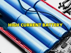
The transformer method is to first perform AC/AC step-down through a transformer, while the switching method is to rectify the AC voltage directly with a diode bridge rectifier. Since the power consumption of ordinary households is AC100V or AC200V, the diode bridge rectifier must have specifications that can withstand high voltage battery or high voltages.
Next, smooth the DC voltage (pulse voltage) with a capacitor. Capacitors also require high-voltage-resistant capacitors. Then, the DC voltage is chopped (cut) by the ON/OFF of the switching element, and the voltage is stepped down by a high-frequency transformer and sent to the secondary side. At this time, the chopping waveform becomes a square wave.
The switching elements use higher frequencies (eg 100kHz) compared to household frequencies (50/60Hz). Due to the high frequency operation, miniaturization and weight reduction of the transformer can be realized. The square wave is half-wave rectified by a rectifier diode on the secondary side, and then smoothed by a capacitor, and a DC voltage is output.
The switching method is a method of using a control circuit to control the switching element to obtain a stable and expected DC output (for example, DC12V). Compared with the transformer method, the switch method is composed of switching elements and control circuits, and the circuit structure is more complicated. However, since a small transformer can be used based on high-frequency control, it contributes to the miniaturization of the equipment, which is a great advantage of it.
What is feedback control?
Switching AC to DC converter confirms the actual output DC voltage value and control the switching elements based on the voltage information to ensure stable realization of the specified DC output. This mechanism of confirming the output voltage value to control the switching element is called feedback control (FB control).

Switching AC to DC converter rectifies the AC voltage through a diode bridge and smooth it through a capacitor to convert the AC voltage to a DC voltage. Then, the DC voltage is chopped (ON/OFF) by a switching element, then stepped down by a high-frequency transformer and transmitted to the secondary side, and then smoothed by a capacitor to output a predetermined DC voltage. The FB control circuit detects whether the actual output voltage value reaches the specified target voltage value.
When the actual output voltage value is lower than the target voltage value, the switching element is controlled to make the ON time longer. In this way, the output voltage value will rise. Conversely, when the voltage is higher than the target voltage value, the control ON time is shortened. In this way, the feedback control circuit constantly checks the actual output voltage value, and adjusts the ON/OFF time of the switching element according to the value to ensure the stability of the target output voltage value.
What is light load mode?
Switching AC to DC converter and DC to DC converter perform voltage chopping and capacitor smoothing by ON/OFF conversion to stably provide the target output voltage value. However, this switching generates momentary leakage current (shoot-through current) during ON/OFF. That is to say, the more ON/OFF times per unit time, the greater the loss caused by leakage current and the lower the efficiency.
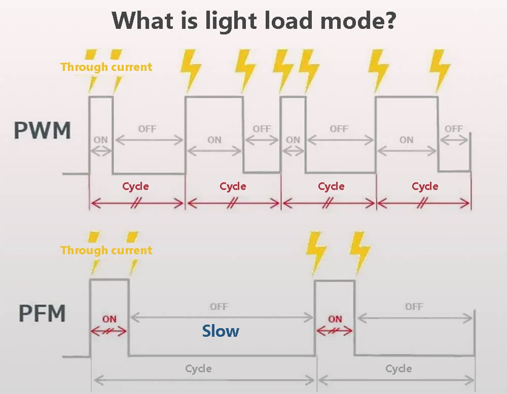
When the period is constant (PWM control), even if the ON/OFF time ratio changes, the number of times is constant per unit time. As a result, the amount of self-dissipation is also constant, and this loss of switching leakage current at light loads reduces efficiency. Therefore, in the case of using less current, frequency modulation (PFM control) is used to lengthen and slow down the cycle, thereby reducing the number of ON/OFF transitions per unit time and reducing losses. This technique is called light load mode.
The use of PWM and PFM can further improve the efficiency according to the situation. For example, when the load is high (current is used), the cycle-constant PWM control is used, and the cycle-variable PFM control is used when the load is light (current is not used).