Skip to content

The development trend of electric vehicle on board charger
China’s new energy electric vehicles are developing rapidly. By 2022, the annual sales volume of China’s new energy electric vehicles was 6.887 million, a year-on-year increase of 93.4%, and the market share reached 26%. It is predicted that the total sales of electric vehicles in China will exceed 9 million in 2023, a year-on-year increase of 35%, and the penetration rate will reach 32.6%.
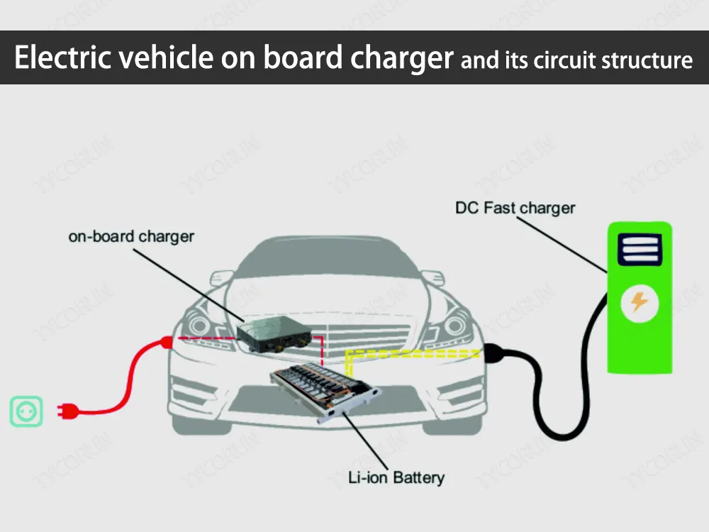
In 2022, the installed capacity of electric vehicle on board chargers reached 5.1287 million sets, a year-on-year increase of 77.6%. It is estimated that the market size will reach 30 billion RMB in 2023, with huge potential. When using AC charging piles to charge, electric vehicles need to be equipped with on board chargers.
It is the core component of the internal energy conversion of the electric vehicle. It can fully charge the power wheels battery safely and automatically. According to the data provided by the battery management system (BMS), it can automatically adjust the charging current and voltage parameters, so as to make corresponding instructions to complete the charging process.

Considering the space constraints and safety requirements of its own products, electric vehicle on board chargers need to have strict requirements in terms of power density, charging efficiency, weight, volume, output voltage and current, safety and reliability. In order to meet the needs of users and car manufacturers, electric vehicle on board chargers have experienced many challenges, such as:
- How to achieve high power density of electric vehicle on board charger:
It requires selecting a high-frequency and high-efficiency circuit topology and optimizing the design of the circuit structure. - How to achieve bidirectional flow of electric energy to use BMS to power some AC equipment:
It requires the battery charger to have a bidirectional topology. - How to reduce volume under higher power index:
It requires the electric vehicle on board charger to move towards intelligence and high integration.
In order to realize fast two-way charging of electric vehicles, charging piles, batteries and electric vehicle on board chargers have all undergone technical improvements.
Charging piles are rapidly developing towards high power, high voltage, two-way, wide range and other characteristics. Batteries are being upgraded towards high voltage battery (400V→800V) and high power. New materials and other aspects have also made great progress, and are developing in the direction of bidirectional charging and discharging, intelligence, and integration.
At present, there are mainly the following types of electric vehicle on board chargers (OBC), as shown below:
In terms of the power, 3.3kW and 6.6kW products are currently the mainstream. In terms of output voltage, the electric vehicle on board charger products of some companies have been gradually equipped with 800V complete vehicles.
In addition, as the competition among manufacturers intensifies, China has introduced SiC power devices on electric vehicle on board chargers. For example, companies such as Weimax, Inpower, and Xinrui Technology have released electric vehicle on board product solutions based on silicon carbide.
Circuit structure of electric vehicle on board charger
Electric vehicle on board chargers generally adopt a two-stage structure (as shown in the figure below). The primary stage PFC is mainly responsible for power factor correction, and generally outputs 400V DC. The subsequent DC/DC circuit takes power from the PFC bus to realize the isolation and voltage regulation functions.
Since the load connected to the DC/DC is a battery, which generally outputs 200-500V high-voltage direct current, the subsequent stage must adopt a high-efficiency and wide-range isolated DC/DC topology.

Primary PFC circuit
The more common topology in PFC circuits is the boost topology, which is divided into traditional bridge boost PFC, interleaved parallel boost PFC, bridgeless boost PFC, dual bridgeless boost PFC, totem pole boost PFC, etc.
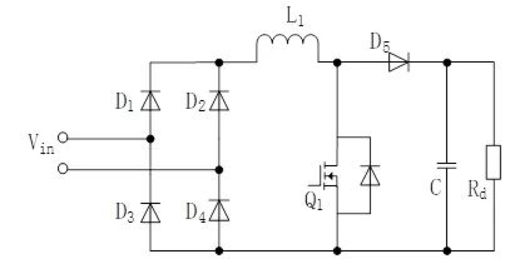
(1) Traditional bridge boost PFC:
When Q1 is turned on, the positive half-cycle conduction path is D1, L1, Q1, D4, and the negative half-cycle conduction path is D2, L1, Q1, D3. When Q1 is turned off , the conduction path of the positive half cycle is D1, L1, D5, Rd, D4, and the conduction path of the negative half cycle is D2, L1, D5, Rd, D3.
In each state, the number of switching devices is three, which has the advantage that the circuit topology is easy to control, but there is only one Q1 switching device, and its voltage and current stress are very large, which is difficult to use in high-power scenarios.
(2) Interleaved parallel boost PFC:
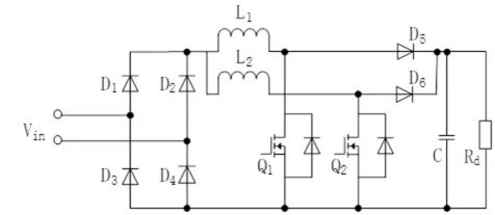
It is composed of two identical boost PFC converters connected in parallel. This topology circuit can reduce the inductance of the PFC. By controlling the currents of the two power inductors to interleave with 180° anti-phase, the input and output current ripple can be reduced, and the size of the EMI filter can be reduced.
This topology is the same as the traditional bridge in other control and power directions, but the number of switching devices is increased.
(3) Bridgeless boost PFC:
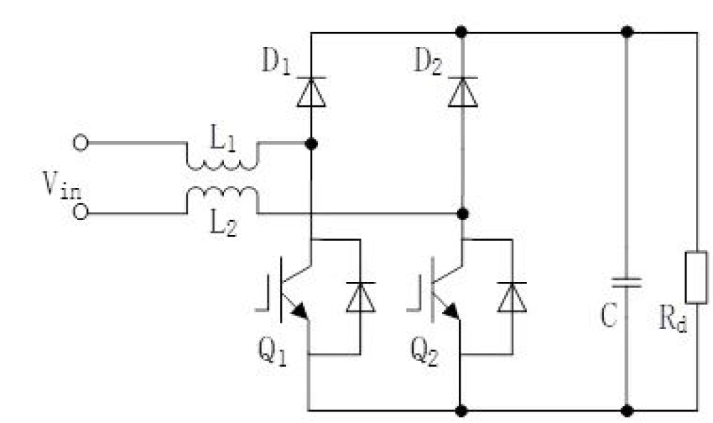
The rectifier bridge of the bridged PFC is removed, reducing the number of switching devices. Working in the positive half cycle, when Q1 is off, the power path is L1, D1, Rd, Q2, L2. When Q1 is on, the power path is L1, Q1, Q2, L2. Working in the negative half cycle, when Q2 is off, the power path is L2, D2, Rd, Q1, L1. When Q2 is on, the power path is L2, Q2, Q1, L1.
Compared with the traditional bridge PFC, the switching devices on the conduction path are reduced, which is beneficial to improve the efficiency of the system. For switching devices with anti-parallel diodes, Q1 and Q2 can share a drive signal.
This topology is simple to control, but difficult to sample the current. Moreover, the terminals of the output DC voltage are floating, and the generated common-mode interference will be isolated, so there will be serious EMI problems in the circuit.
(4) Dual bridgeless boost PFC:
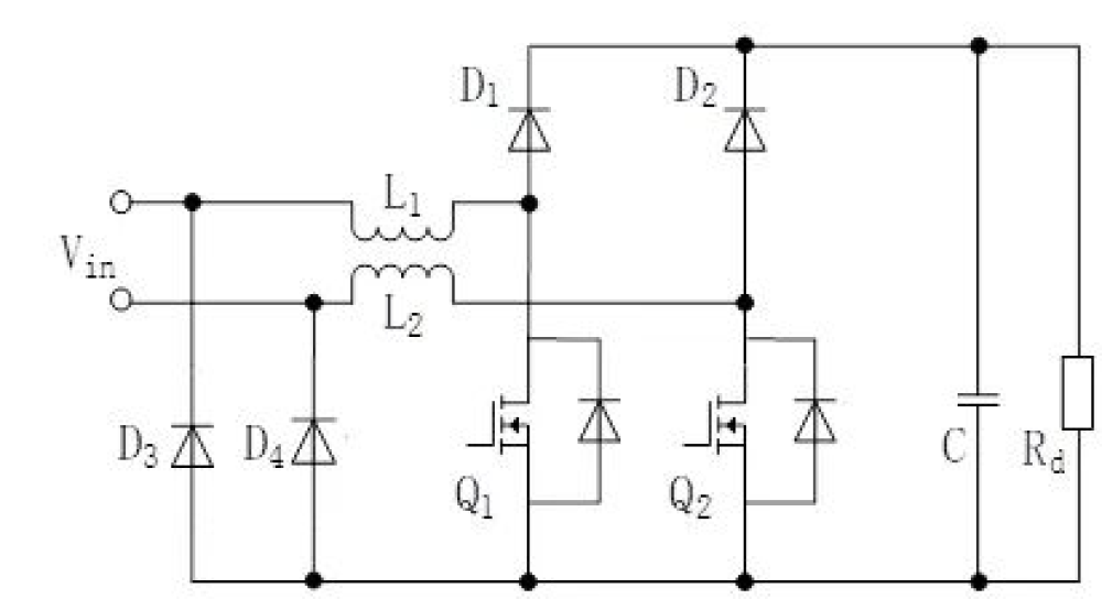
Compared with the bridgeless PFC circuit, the dual bridgeless PFC has improved the EMI. Working in the positive half cycle, when Q1 is turned off, the power path is L1, D1, Rd, D4. When Q1 is turned on, the power path is L1, Q1, D4. Work in the negative half cycle, when Q2 is off, the power path is L2, D2, Rd, D3. When Q2 is on, the power path is L2, Q2, D3.
Its control method is similar to the basic bridgeless PFC. The added diode greatly reduces the noise of the circuit, but the system cost increases.
(5) Totem pole boost PFC:
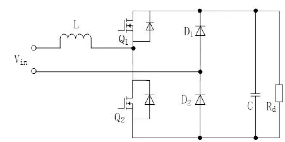
It can solve the EMI problem of bridgeless PFC. Working in the positive half cycle, when Q1 is off and Q2 is on, the power path is L, Q2, D2. When Q2 is off and Q1 is on, the power path is L, Q1, Rd, D2. Working in the negative half cycle, when Q1 is off and Q2 is on, the power path is D1, Rd, Q2, L. When Q1 is on and Q2 is off, the power link is D1, Q1, L.
The topology control is complicated, and the drive of the upper tube needs to be floating, which makes the design difficult and increases the cost, and there is a reverse recovery problem in Q1 and Q2, which is easy to increase the circuit loss.
Secondary circuit DC/DC
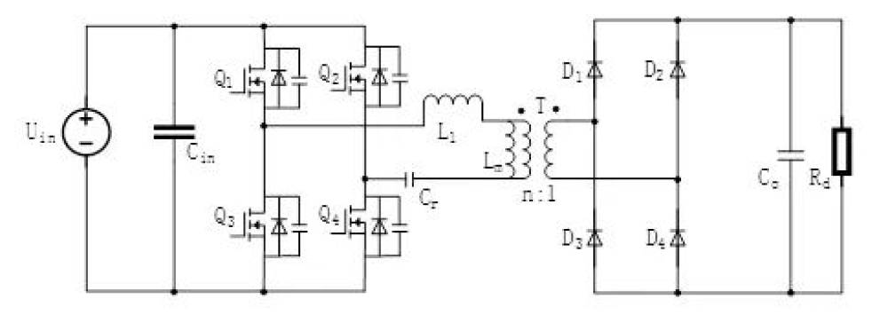
The circuit topology types of DC/DC converters mainly include buck, boost, buck-boost, phase-shifted full bridge, resonant converter and other circuit topologies, while isolated DC/DC converters are more suitable for electric application requirements of vehicle on board charger. Common isolated DC/DC converter topologies mainly include phase-shifted full bridge, dual active bridge circuit, LLC resonant circuit, etc.
(1) Phase-shifted full bridge circuit:
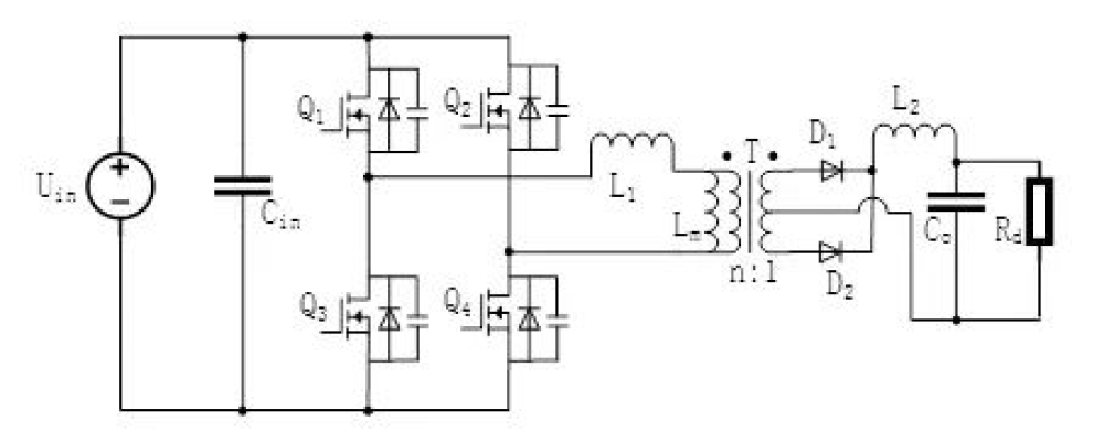
It can realize the wide-range voltage output with the lowest zero voltage. The driving signal of the super-forearm Q1 and Q3 has a phase difference of 180°, and the driving signal of the lagging arm Q2 and Q4 lags behind Q1 and Q3 by a certain phase, and the different phase angles between control drive signals can make the transformer leakage inductance and the switching tube junction capacitance resonate, achieving the soft switching of the switching tube.
The disadvantage is that due to the existence of transformer leakage inductance, the secondary side will lose the duty cycle, and the secondary side diode is prone to voltage spikes. In addition, the LC filter required for the output of this topology will increase the circuit size and increase the loss.
(2) Dual active bridge circuit:
The direction and magnitude of energy flow is controlled by phase shifting of the primary and secondary sides, and zero-voltage turn-on can be achieved. It is often used in bidirectional DC/DC converters in high-power applications. This topology circuit has high power density, high efficiency, and bidirectional power transmission, are widely used in electric vehicles, aerospace and other fields.
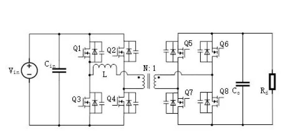
(3) LLC resonant circuit:
It can realize soft switching, and can realize a larger voltage regulation range in a narrow frequency range. It has good load shedding characteristics, and the leakage inductance of the transformer can be reused as the excitation inductance, so the space of the magnetic components is small, and the power density of the converter can be improved, and the efficiency is high and the EMI is small.