Skip to content
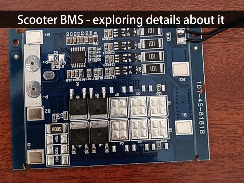
Scooter BMS - exploring details about it
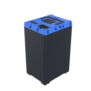
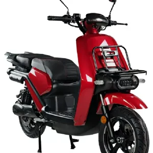
Battery Management System (BMS) for scooter can be shorted as scooter BMS which is needed when we want to keep our scooter’s battery in a good condition.
When batteries are not used correctly, it can affect their capacity, safety, health status, and range. Therefore, when using batteries, a strict BMS is needed to monitor and protect the battery. This system prevents overcharging, over-discharging, overheating, short circuits, etc., while also intelligently controlling charging and discharging. This ensures the battery’s performance is fully utilized and improves its consistency.


Brief introduction of scooter BMS
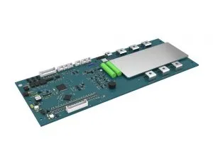
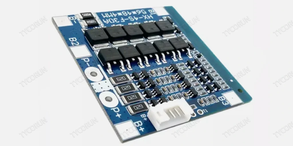
In the industry, the scooter BMS is also referred to as the battery protection board. It is divided into hardware boards and software boards.
A hardware board refers to a protection board without programmable chips, where connections are made according to specific circuits, and the board’s parameters are fixed. This type of protection board generally has low cost and simple functionality, making it difficult to meet special control logic requirements.
On the other hand, the software board builds upon the hardware board by incorporating programmable chips. As a result, in addition to basic functionalities, it can also implement various advanced features.

General structure of scooter BMS
Battery information collection and protection circuit
Analog Front End (AFE): It is used to monitor the voltage, current, and temperature of each battery cell. By collecting data on the cell’s voltage, current, and temperature, it controls the switching on and off of the charging or discharging MOSFETs in case of overvoltage, undervoltage, under-temperature, overcurrent, or short-circuit conditions to protect the battery. The AFE has an integrated balancing circuit, and an external balancing circuit can also be added to adjust the balancing current.
MCU control section
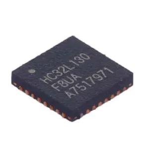
MCU (Microcontroller Unit): The MCU is responsible for charging control and protection. It communicates with the AFE to receive the data on voltage, current, and temperature. The MCU uses this data along with battery charging/discharging models to calculate the SOC (State of Charge) and SOH (State of Health). It reports abnormal battery information and intelligently controls the AFE to manage charging and discharging processes.
Charging and discharging power path
In scooter BMS, “high-side” and “low-side” refer to the positions of the MOSFET devices (switching components used to control the flow of current). Compared to high-side driving, low-side driving is more cost-effective and easier to implement. Many modern AFE (Analog Front End) chips integrate low-side driving, and most two-wheelers on the market primarily use low-side driving.
Communication and sensing
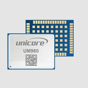
To allow users to monitor the electric vehicle’s battery pack voltage, current, and temperature in real-time, the scooter BMS integrates BT/WiFi communication circuits. Through BT/WiFi, battery information is synchronized in real-time to the user’s mobile device, allowing users to stay informed about their electric vehicle’s battery pack voltage, current, temperature, and other key parameters.
Scooter BMS classification
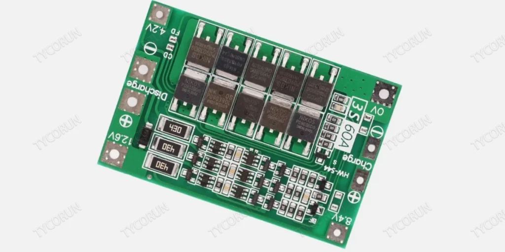
Scooter BMS comes in a variety of types, and the specific choice depends on the type of battery, the application scenario, and the user’s specific needs.
Based on the position of the charging/discharging switch MOSFET, there are two types: high-side drive and low-side drive. According to the positions of the Charging FET (CFET) and Discharging FET (DFET), the scooter BMS architecture can be categorized into four types: high-side series architecture, high-side parallel architecture, low-side series architecture, and low-side parallel architecture.
Introduction to high-Side and low-Side in scooter BMS
In scooters BMS, the terms “high-side” and “low-side” refer to the placement of the MOSFET components (switching devices used to control the current flow). This placement affects the architecture and functionality of the Battery Management System (BMS).
The low-side solution is currently a more mature and easier-to-implement approach, as it can be directly controlled by the AFE (Analog Front End). Most scooters are designed based on the low-side solution. Additionally, many AFEs today have integrated low-side drive capabilities.
However, the low-side protection has a drawback. When the charging or discharging switches are turned off, the battery ground and the system ground are no longer connected. So, when protection is triggered and the charge/discharge FETs are turned off, the battery and system can no longer communicate directly. To maintain communication, isolated communication must be used, which not only increases costs but also power consumption. This can be particularly problematic during under-voltage protection when the battery pack is already low on power. As a result, the low-side solution is typically used in cost-sensitive products that do not require complex communication.
In contrast, the high-side protection still maintains a common ground between the battery and system even when protection is triggered. This allows continuous communication without needing isolated communication and, by disconnecting the battery’s positive terminal, makes the system safer overall.
Series (common terminal) or parallel (separate terminals)
In order to protect the battery, the protection board must be able to actively disconnect the main circuit of the battery. Therefore, within the battery pack, the main circuit must pass through the protection board. To control both charging and discharging, the protection board must have two switches, which control the charging and discharging circuits separately.
In a common terminal protection board, these two switches are connected in series on a single line that connects to the outside of the battery pack, meaning both charging and discharging go through this line.
In contrast, a separate terminal protection board has two lines coming from the battery, which connect to the charging switch and the discharging switch before going outside the battery pack.
The reason for the existence of common and separate terminal protection boards is to reduce costs: typically, the charging current of a battery pack in scooters is smaller than the discharging current. If both switches are connected in series on a single line, then both switches must be rated for the larger current. However, with separate terminals, since the charging current is smaller, a smaller switch can be used. The switches referred to here are MOSFETs, which constitute a major portion of the cost of lithium battery protection boards.

Main functions of scooter BMS
State monitoring
The scooter BMS continuously collects various indicators of the battery, such as voltage, current, and temperature, to assess the current state of charge (SOC) and state of health (SOH). This information helps provide users with accurate estimates of remaining range and assists companies in conducting preventive maintenance activities.
Temperature regulation
Since temperature fluctuations can significantly impact battery efficiency, the scooter BMS implements precise temperature control strategies to maintain optimal operating conditions, thereby extending the battery’s lifespan.
Balancing management
To address potential capacity differences among individual cells, the scooter BMS employs active or passive methods to adjust the charge balance between units, improving overall performance.
Anomaly protection mechanism
When detecting issues such as short circuits or over-voltage situations, the scooter BMS automatically initiates emergency protocols, such as limiting output power or disconnecting power connections, to prevent further damage.
Evolution directions of scooter BMS technology
To maximize the performance of electric two-wheeler batteries, the Battery Management System (BMS) must take on multiple roles from accurately monitoring voltage and current to achieving balance among individual battery cells, and providing comprehensive safety protections such as overcurrent, overvoltage, and temperature monitoring. Additionally, an efficient scooter BMS should support various communication protocols, feature advanced thermal management technologies, and exhibit excellent scalability.
In the field of battery condition monitoring technology, wireless solutions have become an irreversible trend. Innovative wireless approaches not only effectively overcome the cost and maintenance issues associated with traditional wired BMS solutions but also significantly enhance the timeliness and convenience of data acquisition.
Looking ahead, intelligence will be one of the main themes in the evolution of scooter BMS. Relying on algorithm optimization and the application of artificial intelligence technologies, the next generation of smart scooter BMS can respond more flexibly to external changes and provide personalized services. It will also support remote software updates (OTA), allowing users to enjoy the latest feature upgrades without visiting a service center. Furthermore, by integrating advanced predictive analytics tools, potential fault points can be identified in advance, greatly reducing the risk of unexpected downtime.
In summary, the core demands in the battery management field are safety and long-lasting range. Therefore, as scooter BMS technology evolves, it should also find a perfect balance between cost-effectiveness and reliability.

Conclusion:
Increasingly powerful hardware serves as the innovative driving force for electric two-wheelers to continue capturing market share. Improvements in battery energy density, faster charging speeds, and a long battery life significantly enhance the vehicle’s range. This article details an initial introduction to scooter BMS and invites further exploration of this topic in ebike bms.