Home » lithium ion battery knowledge » Understanding the different ebike bms architectures – pros and cons
Understanding the different ebike bms architectures - pros and cons
In recent years, the electric two-wheeler market has ushered in a new upsurge of development. Lithium battery replacement lead acid is also a trend. However, lithium batteries are less safe than lead-acid batteries.
Thus, a strict battery management system (Battery Management System, BMS) is required to monitor and protect lithium batteries. This article will introduce several common ebike BMS architectures as well as the advantages and disadvantages of different architectures and their usage scenarios.

Ebike BMS architecture
Figure 1 shows a typical ebike BMS architecture. It usually consists of batteries, analog front-end, second-stage protection, main control, etc.
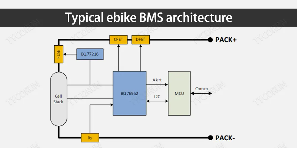
Use AFE to control MOS on-off and secondary protection chip to control three-terminal FUSE fusing for double protection, which is double protection in the true sense. A qualified ebike BMs can pass various functional safety certifications.
Ebike BMS architecture types
High-side serial architecture
The high-side series architecture is shown in Figure 2. Both CFET and DFET are placed on the high side and connected in series, so it is called high side series architecture.
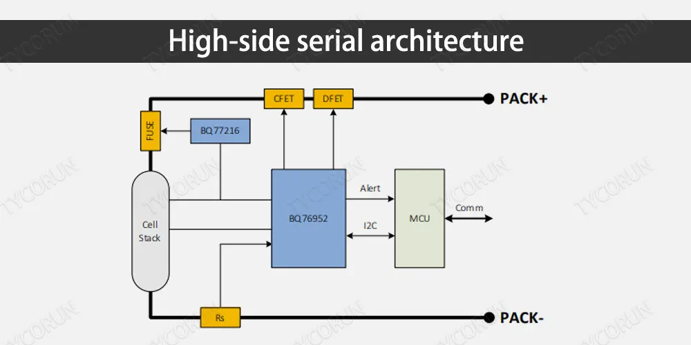
1) BMS does not need to be isolated from external communication, all refer to pack- as the reference ground.2) PACK – there is no short-circuit surge impact problem.
3) The BMS drive circuit does not have a withstand voltage problem, and pack- is always at the same potential as B-.
Disadvantage analysis:
If NMOS is used for high-side control, a boost circuit is required to turn on NMOS, and the driving voltage of gs+B+ can drive NMOS to turn on.
It will increase the cost of the boost circuit. If a PMOS circuit is used, the control is relatively simple, and the cost of PMOS is greater than that of NMOS.
High-side parallel architecture
The high-side parallel architecture is shown in Figure 3. Both CFET and DFET are placed on the high side and connected in parallel, so it is called high side parallel architecture.
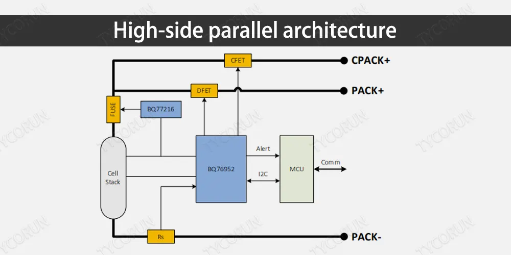
The cost of charging and discharging isochronous interface solution is reduced, the selection of charging MOS refers to the charging current, and the selection of discharging MOS refers to the discharge current. cost will be lower
Disadvantage analysis:
It cannot prevent some misoperations. Charging at the charging port and discharging port will cause fatal damage to the battery cell.
Low-side series architecture
The low-side series architecture is shown in Figure 4. Both CFET and DFET are placed on the low side and connected in series, so it is called low side series architecture.
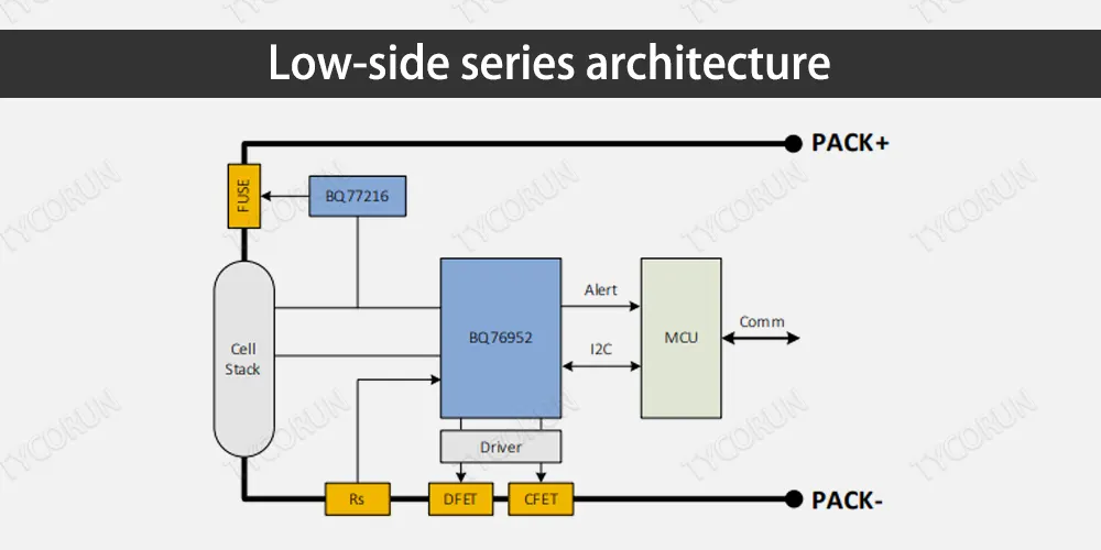
Currently the most widely used ebike BMS solution, with low cost and simple drive control.
Disadvantage analysis:
It is necessary to deal with various problems caused by the potential inconsistency between B- and P- when they are turned off.
Low-side parallel architecture
The low-side parallel architecture is shown in Figure 5. Both CFET and DFET are placed on the low side and connected in parallel, so it is called low side parallel architecture.
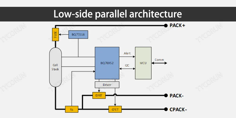
The cost of charging and discharging isochronous interface solution is reduced. The selection of charging MOS refers to the charging current, and the selection of discharging MOS refers to the discharge current. The cost will be lower.
Disadvantage analysis:
It cannot prevent some misoperations. Charging at the charging port and discharging port will cause fatal damage to the battery cell.
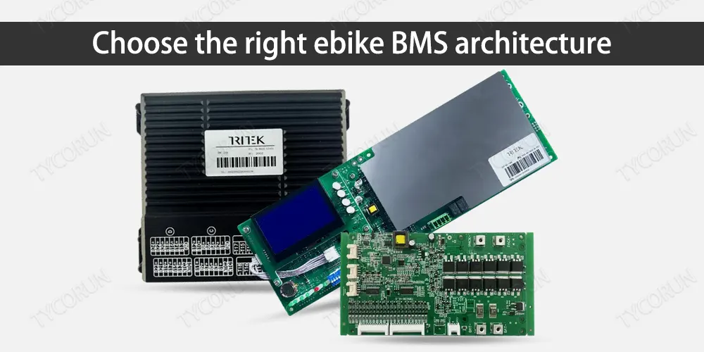
Choose the right ebike BMS architecture
The main difference between the above four ebike BMS architecture architectures lies in two points: one difference is whether the CFET and DFET are placed on the high side or the low side; the other difference is whether the CFET and DFET are connected in series or in parallel.
According to different application occasions, the appropriate ebike BMS architecture should be selected. The main considerations when selecting different ebike BMS architectures are introduced below.
High side or low side
The low-side solution is currently a relatively mature and easy-to-implement solution, and most two-wheelers are also designed based on the low-side solution. At the same time, most of the current analog front-ends also integrate low-side drive capabilities.
However, there is a disadvantage in the low-side protection scheme: when CFET and DFET are turned off, once the protection is triggered to turn off the charging and discharging FETs, the battery side and the system side can no longer achieve direct communication.
Compared with the low-side protection scheme, even after the protection is triggered, the battery pack and the system side are still common ground.
Therefore, mutual communication can still be realized without increasing isolated communication. And disconnect the positive terminal of the battery after triggering the protection, the system is more secure.
Series or parallel
The charge port and discharge port of the series architecture share one port, but the disadvantage is that the number of CFETs and DFETs needs to be selected according to the maximum value of the charge and discharge current.
If the difference between the charging current and the discharging current is relatively large, for example, the charging current of a general electric vehicle lithium battery pack is smaller than the discharging current, and if the series structure is selected, it is necessary to select more CFETs than actually needed, resulting in unnecessary waste.
Compared with the series architecture, the parallel architecture can select the number and type of CFETs and DFETs according to the actual charging and discharging current needs.
The disadvantage is that the reverse current needs to be considered, such as flowing through the body diode of the DFET to the battery core.
To block these current paths, additional circuit assistance is required. In addition, the parallel architecture requires an extra power line and an extra port, which is not suitable for some occasions.
Other ebike BMS architectures
In addition to the above classification according to the positions of CFETs and DFETs, the ebike BMS architecture can also be classified according to the number of analog front ends, whether there is an MCU, etc.
Cascade architecture
According to the number of analog front ends, ebike BMS can be divided into cascade architecture and non-cascade architecture.
The current mainstream ebike BMS, such as electric bicycles, scooters, and self-balancing vehicles, generally use 10S, 14S or 16S battery packs, and a BQ769x2 can support them. Therefore, for the current mainstream ebike BMS, the above-mentioned single AFE solution can be used.
Figure 2 ~ Figure 5 are all non-cascaded architectures. However, for some applications that require relatively large power, such as electric light motorcycles or electric motorcycles, the voltage is usually higher than 60V.
It is necessary to use a battery pack higher than 16 strings to achieve greater power, and a single BQ76952 is not enough to support it. It is necessary to use two chips for cascade use, that is, to adopt a cascade ebike BMS architecture.
Independent architecture
According to the presence or absence of MCU, ebike BMS can be divided into independent architecture and non-independent architecture. Figure 2 ~ Figure 5 all work with MCU, so they are all non-independent architectures.
In Figure 7, the AFE works independently from the MCU, so it is a standalone architecture. When the BQ769x2 works in stand-alone mode, it can still monitor the battery status and control the charge and discharge FETs.
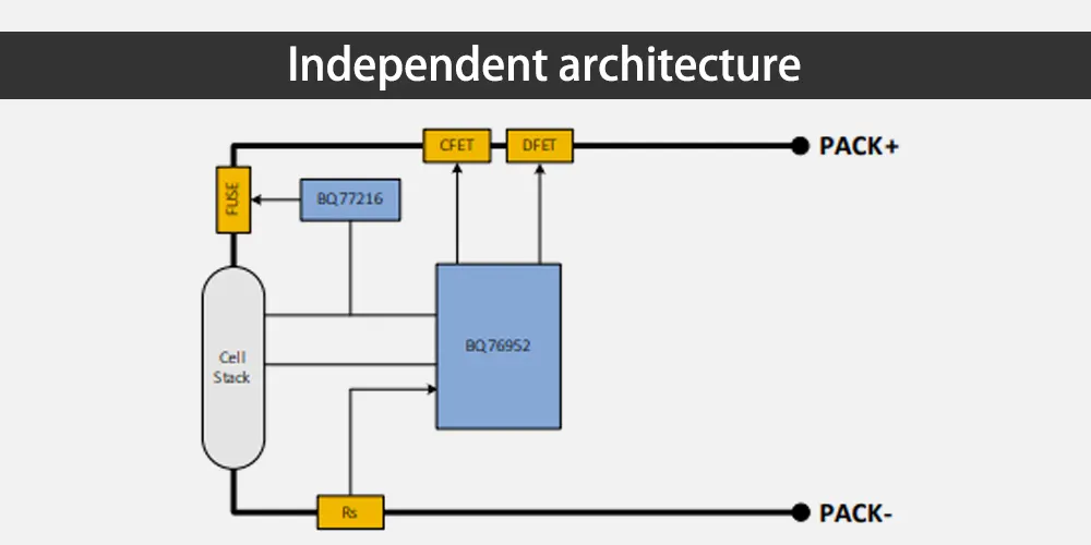
When the protection condition is triggered, the FETs are automatically controlled to turn off to implement protection, and when the protection condition is removed, the FETs are automatically restored to conduct.
The advantage of the independent ebike BMS architecture is that one MCU can be saved, which is suitable for applications with strict cost requirements. However, due to the lack of MCU, there is a loss in flexibility. Users need to choose an independent or non-independent ebike BMS architecture according to actual needs.
Summary
As the battery swapping model becomes more sophisticated, users can expect e-bike battery management systems (BMS) to become more efficient and cost-effective in the near future. The development of more advanced BMS technology will also lead to longer battery life, better performance and improved safety.