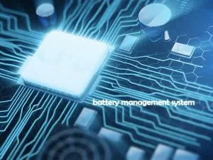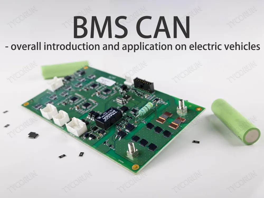

What is a CAN
CAN, that is, Controller Area Network, means the controller area network bus. Based on the reliability and real-time performance of the CAN/485 bus in data communication, usually the BMS communicates with other control modules such as the vehicle controller (VCU) through the CAN bus.
However, due to the large number of nodes in the power battery pack BMS, the topology of the BMS CAN network is relatively complex, which can easily lead to communication failures in the entire system, resulting in real-time battery monitoring, status statistics, online diagnosis and early warning, charging and discharging and pre-charging control by the BMS. etc. are affected.
The interconnection of battery packs and crosstalk such as inverters will cause great signal interference on the BMS CAN bus. When there are too many load nodes on the battery pack, it will also lead to communication congestion. In order to ensure the quality of communication, it is usually necessary to add an isolation device between the BMS CAN transceiver and the micro controller.
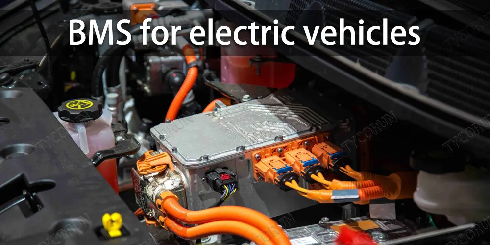
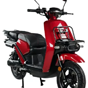
BMS for electric vehicles
As an electronic component for real-time monitoring, automatic balancing, and intelligent charging and discharging, BMS plays important functions such as controlling charging and discharging, ensuring safety, prolonging life, and calculating remaining power. It is an indispensable and important component in power batteries and energy storage battery packs.
Through a series of controls, the normal operation of the energy storage solutions is guaranteed. The BMS monitors and controls the charging and discharging process of the battery through the collection and calculation of parameters such as current, voltage, temperature, and SOC, and analyzes the status of the battery, so as to protect the safety of the battery and improve the overall performance of the battery.
Nowadays, with the development of energy storage technology, the development of BMS has also entered new fields. Usually, the BMS system is mainly composed of three parts: BMS controller, battery pack, and BDU management unit.
The topology of BMS hardware is mainly divided into centralized and distributed:
Centralized topology: Connect all electrical acquisition components to the master controller, and transmit voltage, current and temperature to the master controller. The information interaction between the acquisition module and the master control module is directly realized on the circuit board. The circuit design is relatively simple, and the security and stability of BMS is low, which makes it susceptible to interference.
Distributed topology: It contains master controller and slave controller. One battery pack module is equipped with a slave controller. The master controller is only connected to the communication wiring harness.
The battery module accessories that collect temperature and voltage are in charge of the slave controller, and finally transmit the collected signals to the main control module through the BMS CAN bus, with high channel utilization and flexible configuration.
One end of the vehicle power battery BMS is connected to the battery, and the other end is connected to the vehicle controller and electronic system, and communicates with the vehicle master controller, motor controller, energy control system, and vehicle display system in real time through the BMS CAN bus interface.
Compared with consumer batteries and energy storage batteries, power batteries need to work in high temperature and vibration environments, and are generally modular batteries. One set has multiple cells, and it needs to deal with cells, collisions, BMS CAN, water pumps, high voltage battery, and insulation, so the requirements on reliability and stability are higher.
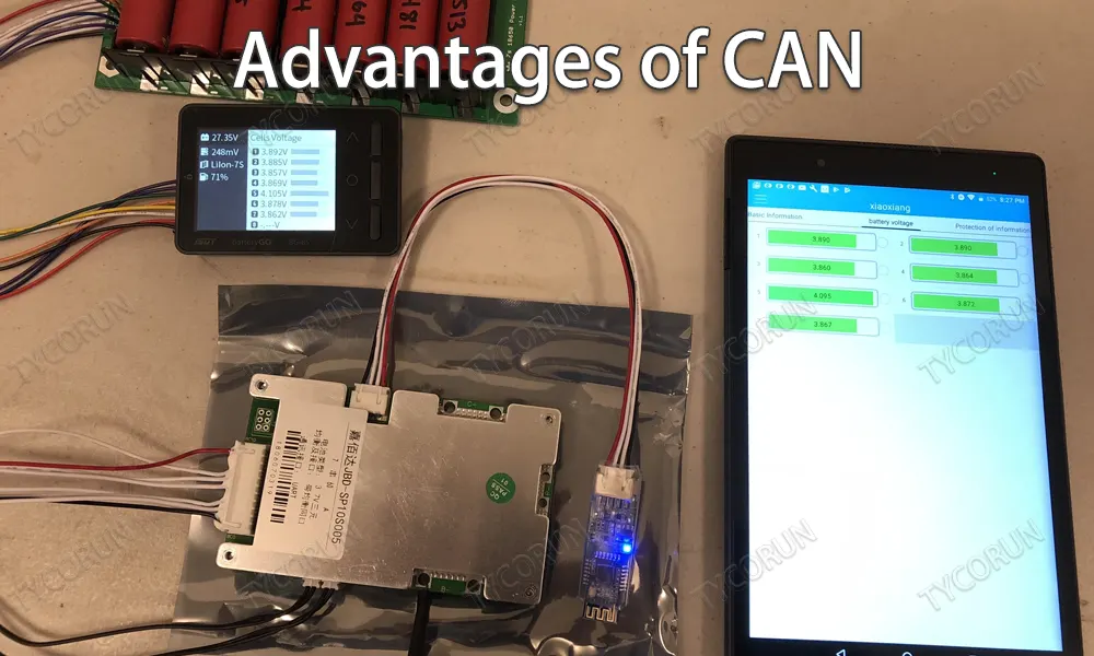
Advantages of BMS CAN
BMS CAN is a serial communication bus. The BMS CAN bus enables robust and flexible communication in harsh application environments or environments with severe battery interference.
● The BMS CAN bus uses differential signals, so it has a strong anti-noise ability. BMS CAN bus is mainly used in industrial and automotive fields. It is also widely used in consumer electronics and commercial fields.
● The BMS CAN bus defines the data link layer and the physical layer in the OSI model, providing the underlying network solution for high-speed in-car communication.
● One of the purposes of developing the BMS CAN bus is to minimize the amount of cable routing. In practical use, the BMS CAN bus can use twisted pair to transmit serial data.
● The BMS CAN bus uses multiple main buses, in other words, the nodes on the BMS CAN bus are not divided into the host and the slave. Any node BMS CAN actively send messages to other nodes on the CAN bus at any time.
● BMS CAN bus is a CSMA/CD protocol. Therefore, each node on the bus can detect whether a conflict has occurred. If a conflict occurs, it will wait a certain amount of time before attempting to resend the message. Conflict detection is achieved through priority arbitration based on message identifiers.
Based on the communication function of BMS CAN bus, the battery management system can better manage and monitor the function of each battery unit in the battery pack. The BMS CAN output real-time data through the hardware link of the CAN bus for other devices on the car or external devices to receive and use.

The role of CAN in electric vehicle BMS
On an electric vehicle, there are many functional modules that work together to enable the vehicle to run properly. Some of these function modules work independently, and some work in conjunction with other function modules in the vehicle. And all the functional modules have communication functions.
It is necessary to ensure the normal communication and data transmission between each function module on the electric vehicle, because in this way, the best working state of each function module can be achieved, and the appropriate management and monitoring of each vehicle function module.
In electric vehicles, both the OBD (Onboard Diagnostis) module and the Electroni Control Unit (ECU) use the CAN bus to transmit data. As one of the three major systems of electric vehicles, the BMS also uses the CAN bus to complete the transmission of real-time data and control commands.
BMS CAN network is applied to electric vehicle charging machine, mainly according to the working principle of charging machine and combined with the working characteristics of BMS CAN bus, to develop a suitable working flow chart based on BMS CAN bus communication.
1. In the battery charger, the communication network (CAN1) between the main controller and the battery management system: it is mainly used to realize the data exchange between the charger and the vehicle battery management system, and provide parameter information for the power battery charging.
2. The communication network between the main controller of the charger and the charging monitoring system (CAN2) : to realize the real-time data acquisition, monitoring and control functions of the monitoring center and the charger, to grasp the working status of the charger through the monitoring center in real time, and to indirectly obtain the battery information through the charger.
3. The communication network between the main controller of the charger and the power module (CAN3) : achieve the data exchange between the main controller of the charger and the independent power module, and realize the software current sharing scheme based on the BMS CAN bus, in which the power modules are used as working modules and multiple power modules are used as standby power modules.
To sum up, BMS CAN bus is an important part of modern vehicles, especially electric vehicles. Because there are more electronic modules on electric vehicles, they need to constantly communicate with each other to achieve optimal performance. It is necessary to use the BMS system based on CAN bus to monitor the working state of electric vehicle battery pack in real time.