The 4680 battery is a new generation of cylindrical batteries with a diameter of 46mm and a height of 80mm by Tesla, Tesla is also one of the Top 20 pouch battery manufacturers in the world. Compared with other cylindrical batteries.
The 4680 battery adopts the design of electrodeless battery lugs, also known as full battery lug. The battery directly draws current from the current collector on the positive/cathode, which greatly increases the current path and shortens the distance between the tabs, thereby greatly improving the battery power. In fact, the square wound battery also has an full battery lug design structure.

Full battery lug design
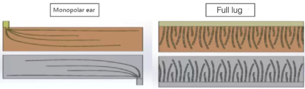
As shown in the figure, the commonly used method to improve the battery rate in the structural design of the square wound power lithium battery is to change the current flow path in the current collector and increase the current carrying area of the battery lug. There are two main schemes: one is the full battery lug design scheme, and the other is the multi-battery lug design scheme.
The full battery lug scheme does not require die-cutting of the uncoated current collector, and the blank part of the positive or cathode is welded to the battery lug by ultrasonic welding, and the assembly and welding process is simpler. This article briefly introduces the assembly process of the full battery lug square wound battery.
Winding
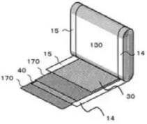
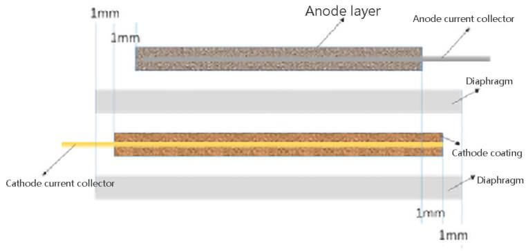
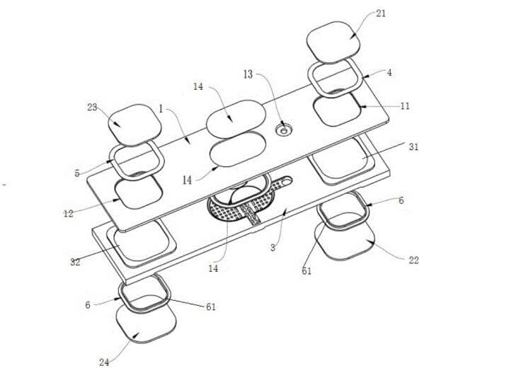
When the battery is wound with full battery lug, the arrangement of the battery lug piece and the diaphragm is as shown in the figure. The blank side (14) of the cathode material (40) is welded on the positive and negative conductive fluids as a lug, respectively, and the positive and cathode pieces are separated by a diaphragm (170), and the positive and cathodes are respectively leaked from both sides of the winding core. The cathode current collector is directly connected to the positive and cathodes of the battery through the current collector.
From the perspective of battery lug, the power characteristics of the battery are improved, so that the distance that the current flows is short, and the current density distribution is uniform at high rates, which can achieve high power density and small heat generation of the battery lug piece.
During the winding process, a certain tension is applied to the diaphragm to ensure the orderliness between the anode sheet, the diaphragm and the cathode sheet.
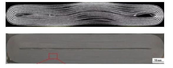
The shrinkage of the diaphragm in the direction of tape travel is large, which will cause the diaphragm to severely squeeze the battery lug pieces, resulting in the deformation of the battery cell after winding.
As shown in the figure, this can lead to quality problems such as fast self-discharge, low capacity, and poor cycling performance, with obvious deformation problems for thicker windings.
In addition, the poor consistency of the thickness of the cells in the loose state will affect the cell insertion process, increase the difficulty of the process, and may cause damage to the cells when entering the case. Therefore, winding tension control is very important.
In the winding process experiment, the core needs a lot of testing to ensure product quality, mainly including:
Dimensions of the cell
Including height, width, thickness, tape width and position, the uniformity of blank collectors, etc. These dimensions can be measured directly and are related to the winding process and the accuracy of the equipment.
Length of battery lug piece and diaphragm
In order for the lithium ions diffused from the anode to have correspondingly received and embedded lattices in the cathode, the cathode must completely wrap the anode and have a certain size margin. In order to avoid the occurrence of short circuit, the diaphragm must be wrapped by the cathode.
The wound cell must ensure that the cathode has a margin compared with the anode in the length direction, and the diaphragm must also wrap the cathode. The relative position of the battery lug pieces is very important, including the length of the diaphragm, the relative position between the positive and cathodes, and the relative size with the cathode. The battery lug piece coating specifications, winding process, etc. affect the size.
Battery lug piece width
In the width direction, the cathode needs to exceed the anode by a certain margin, and the diaphragm needs to exceed the cathode by a certain margin. The alignment in the width direction is determined by the winding process accuracy. When the accuracy is high, the margin size is smaller and the battery energy density is higher.
However, to avoid potential safety hazards and reduce the battery safety factor, the process accuracy must be ensured. The alignment of the battery lug pieces of each layer of the core is generally detected by X-rays on all four corners of the core. When the relative size of the width between the positive and cathodes does not meet the requirements, the equipment will automatically alarm and reject the defective products.

The quality of the winding core
During the processing of the battery lug piece, the defective battery lug piece such as single-sided coating and leakage foil will be marked, and the single battery lug piece will be curled and thrown out during winding.
However, defective battery lug pieces still often appear in the winding core, and the quality of the winding core can be checked to eliminate the unqualified products, which can further ensure the quality.
The main reason for the abnormal quality inspection is the defective products produced during the battery lug piece processing, such as the coating surface density does not meet the requirements, the single-sided coating, the battery lug piece has defects such as tape.
The battery lug piece cuts off burrs
The battery lug piece cutter will wear for a long time, which will affect the cutting effect. Therefore, the cutter needs to carry out life management, and regularly check the cutting quality to avoid burrs. The general observation process of cutting burr is: take the cutting battery lug piece, observe the cutting surface under an optical microscope, and detect whether there is a burr.
Regarding the burr control standard, generally the size of the burr is less than half of the thickness of the diaphragm, but some manufacturers have stricter control requirements, and the burr does not exceed the coating.
Other defects inside the core
Such as battery lug piece bending, coating yin and yang surfaces, foreign matter, etc.
Core pre-compression
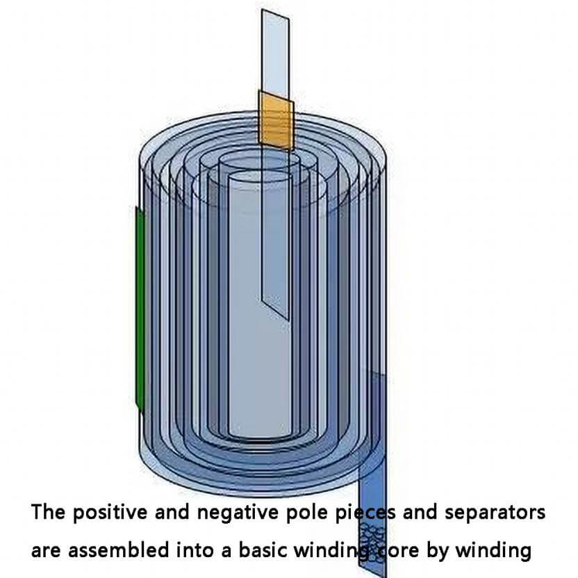
The positive and negative battery lug pieces and diaphragms are assembled into a basic winding core by winding. Afterwards, the cells are generally pre-stressed and shaped.
The core is shaped by at least one hot pressing and/or at least one cold pressing. The pre-compression shaping process is as follows: place the wound or laminated cells on the template, set the pressure of the booster cylinder and the temperature of the template,
Then, the upper and lower templates shape the cells under a certain pressure and temperature, so that the thickness of the cells is consistent, the elasticity of the cells is reduced, the qualified rate of the cells is reduced, and the consistency of the thickness of the finished cells is ensured.
The hot pressing temperature is 70~100℃, the time is 30~120s, and the core pressure is 0.1~1MPa. The main purposes of cell thermoforming include:
(1) Improve the flatness of lithium-ion batteries, so that the thickness of the cells meets the requirements and has high consistency.
(2)Eliminate the wrinkles of the diaphragm, drive out the air inside the battery, make the diaphragm and the positive and negative battery lug pieces closely fit together, shorten the diffusion distance of lithium ions, and reduce the internal resistance of the battery.
In the pre-pressing process experiment, the detection items mainly include whether the battery lug piece is broken, the thickness of the diaphragm, and the change of air permeability; whether the thickness of the cell meets the requirements for entering the shell, etc.
The microporous structure on the diaphragm is an important channel for ions to and from the positive and cathodes. The gas permeability of the diaphragm will directly affect the performance of the battery. The gas permeability of the diaphragm refers to the amount of gas that the diaphragm passes through under a certain time pressure.
If the air permeability of the diaphragm is not good, it will affect the transfer of lithium ions between the positive and cathodes, which will affect the charging and discharging of the lithium ion battery.
During the hot pressing process, the diaphragm may be severely compressed, and the thickness of the diaphragm changes greatly, causing the micropores to be blocked, and the diaphragm will become transparent when observed with the naked eye. transmission.
If the coiled cell battery lug piece is relatively brittle, the cell is prone to powder drop or even breakage during the hot pressing and shaping, which will increase the internal resistance of the battery because the electron transmission is limited.
Cell thermoforming must avoid this from happening. These two aspects require that the smaller the hot-pressing pressure, the better, and the shorter the time, the better.
On the other hand, the hot-pressing shaping must make the cell shape, the thickness of the cell meets the process requirements, the elasticity of the cell is reduced, and the consistency of the thickness of the finished cell is ensured. Therefore, process parameters such as pressure, time and temperature need to be optimized.
Withstand voltage insulation test
Generally, when the cell is hot-pressed and shaped, the insulation withstand voltage test is performed on the cell at the same time to detect whether there is a micro-short circuit inside the cell. If there are tiny metal foreign particles inside the cell, when the cell is pressed down, the cell diaphragm is pierced, and it is easy to detect micro-short-circuit defective products.
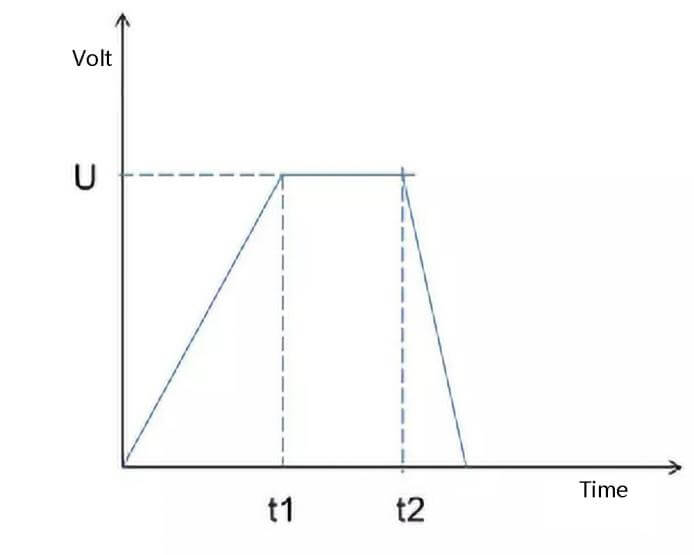
The insulation withstand voltage test generally uses a safety gauge. During the test, the instrument applies a voltage to the cell, this voltage lasts for a specified period of time, and then checks whether the leakage current is maintained within the specified range, and judges that the positive and cathodes of the cell have No short circuit. In general, the applied voltage is shown in Figure:
①In a certain time t1, apply voltage to the cell from 0 to U.
②The voltage U is maintained for a period of time until t2.
③ After the test is completed, cut off the test voltage and discharge the stray capacitance of the cell.
In the test, since the positive and negative battery lug pieces are close to each other, only the diaphragm is separated by 15-30 μm, and a certain capacitance (stray capacitance) will be formed inside the bare cell.
Due to the existence of capacitance, the test voltage must start from “zero” and rise slowly to avoid excessive charging current. The larger the capacitance, the longer the ramp-up time t1, and the lower the voltage that can be increased at one time.
When the charging current is too large, it will definitely cause misjudgment by the tester and make the test result incorrect. Once the stray capacitance of the cell under test is fully charged, only the actual leakage current remains. Since the DC withstand voltage test will charge the cell under test, be sure to discharge the cell under test after the test.
The diaphragm has a certain withstand voltage strength. When the loading voltage is too high, the diaphragm can definitely be broken down and a leakage current will be formed. Therefore, first of all, the cell insulation test voltage should be lower than the breakdown voltage. As shown in the figure, when there is no foreign matter between the positive and cathodes, the leakage current is less than the specified value under the test voltage, and the cell is judged to be qualified.
If there is a certain size of foreign matter between the positive and cathodes, the diaphragm is squeezed, the distance between the positive and cathodes is reduced, and the breakdown voltage between the positive and cathodes will drop. If the same voltage is still applied, the leakage current may exceed The set alarm value.
By setting parameters such as test voltage, it is possible to statistically analyze and judge the size of foreign objects inside the cell, and then according to the actual product production status and quality requirements, test parameters can be set to formulate quality judgment standards.

In the test, the main parameters include the voltage ramp-up time t1, the voltage holding time t2, the loading voltage U, and the alarm leakage current. As mentioned above, t1 and U are related to the stray capacitance of the cell. The larger the capacitance, the longer the ramp-up time t1 is, and the lower the loading voltage U is.
Moreover, U is also related to the withstand voltage strength of the diaphragm itself. Generally, the thinner the diaphragm, the lower the withstand voltage strength, and the test voltage U should also be lower. The alarm current setting needs to consider the capacitor charging current. The larger the charging current, the larger the alarm current should be. Otherwise, it will cause misjudgment, and the qualified product will be judged as unqualified, which will affect the product qualification rate.
When the moisture content of the diaphragm is large, it is easy to form a large leakage current. If there is foreign matter inside the test cell, it will cause an internal short circuit and the diaphragm will be broken down, as shown in the figure.
Therefore, the insulation withstand voltage test of the bare cell is an important step in the product process inspection, which can detect unqualified products and improve the safety factor of the final battery product. The actual test needs to consider many factors such as parameter setting, judgment standard and so on.
Battery lug welding
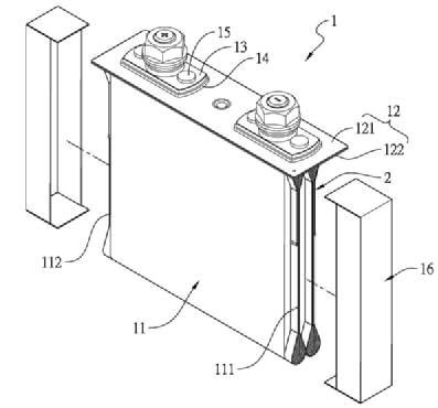
As shown in the figure, assemble the top cover, and weld the positive blank current collector and the positive bus bar together by laser welding or resistance welding.
Weld the cathode blank current collector and the cathode bus bar together. When the design capacity is relatively large, the two winding cores can be connected in parallel.
When welding, multiple winding cores can be welded together in parallel first, or each winding core can be welded separately (for example, two winding cores are welded on 232 busbars respectively), and multiple winding cores can be connected in parallel after laser welding.
The welding process needs to select the appropriate laser and welding process parameters according to the current collector material, shape, thickness, tension requirements, etc. Including welding speed, waveform, peak value, welding head pressure, etc. to set reasonable welding process parameters to ensure that the final welding effect meets the requirements of the power battery.
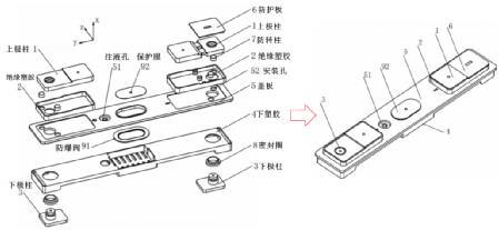
The top cover is as shown in the figure. Its structure is mainly composed of top cover plate, positive and negative battery lugs, explosion-proof device, liquid injection hole, etc. Generally, the battery lug part includes a flip device (OSD), a current cut-off structure (CID) and a short-circuit device. (Fuse) and other institutions.
Generally, there are two battery lug perforations on the top cover of the battery corresponding to the positive battery lug and the negative battery lug. out and electrically insulated from the top cover sheet, and a short-circuit component is arranged near the negative battery lug.
When the internal pressure of the power battery increases, the short-circuit part moves upward, making the positive and cathodes of the power battery form a loop, and a large current is generated in the loop, so that the connecting parts are fused, thereby cutting off the main circuit.
Wrap the insulating film and into the case
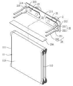
Wrap an insulating film between the laser welding and the shell, and use the insulating film to cover the winding core of the welding battery lug, as shown in the figure, including:
(1)The thickness of the insulating film in contact with the positive and negative busbars should be larger, for example, not less than 0.1mm; (2) The thickness of the rest of the insulating film on the winding core can be thinner, such as 0.05mm. Then, put the core into the casing, as shown in Figure 11.

Top cover laser welding
The top cover and the shell are welded together by laser, as shown in the picture. Laser welding has many advantages such as high energy density, good power stability, high welding precision, and easy system integration.
The top cover sealing welding seam is the longest welding seam in the square aluminum battery, and it is also the welding seam that takes the longest time to weld. The welding speed is relatively low, the thermal cycle time of the weld is relatively long, the molten pool has enough time to flow and solidify, and the shielding gas can cover the molten pool well, and it is easy to obtain a smooth, full and consistent weld.
Speeding up the welding heat cycle time shortens, the melting process of the metal is more intense, the spatter increases, the adaptation to impurities will be worse, and it is easier to form spatter holes. At the same time, the shortening of the solidification time of the molten pool will cause the weld surface to be rough and consistent. reduce.
When the laser spot is small, the heat input is not large, and the spatter can be reduced, but the depth and width of the weld is relatively large, and the welding seam width is not enough; when the laser spot is large, a larger laser power needs to be input to increase the width of the weld. However, at the same time, it will lead to increased welding spatter and poor welding surface forming quality.

At present, the battery shell and the top cover are mainly made of aluminum alloy, and the difficulty of welding is that the reflectivity of the aluminum alloy to the laser is extremely high. During the welding process, the sensitivity of pores is high, and some defects will inevitably occur during welding, the most important ones are pores, hot cracks and explosions.
In the welding experiment, the appearance of the weld, the welding strength (tensile method), the size and morphology of the molten pool (metallographic observation), and the tightness are generally checked. In addition, after welding, X-rays are used to inspect various parts of the interior of the battery.
Injection and pre-filling
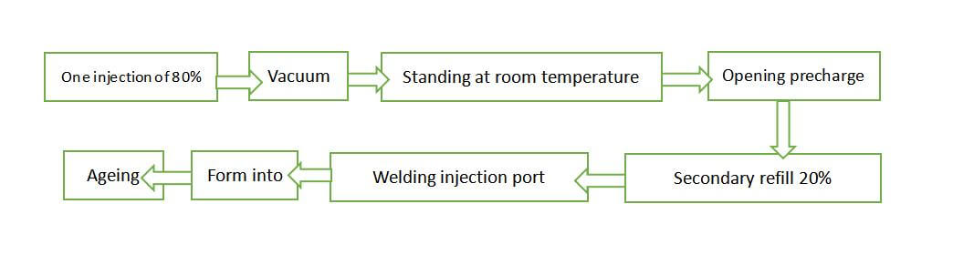
After the battery is dried, liquid injection and pre-charging are carried out. The liquid injection and pre-charging process is shown in the figure.
Specific process parameters include:
One injection
For the first injection, the injection volume is 80% of the total electrolyte. The injection machine first evacuates the electrolyte to remove air bubbles, then evacuates the battery chamber, and then injects nitrogen under pressure. Inside the battery, the electrolyte is automatically injected into the battery twice.
Vacuuming
After the liquid injection is completed, vacuum the battery for 3 minutes to allow the electrolyte to fully infiltrate.
Standing at room temperature
the electrolyte continues to infiltrate the pores of the battery lug piece.
Opening pre-charging
The charging and discharging equipment is placed in a pre-charging room with an ambient dew point of -60 °C, and the indoor exhaust fan is used to exhaust air, and dry air is continuously replenished. The pre-charging procedure is 0.2C charging for 60min, and the SOC is about 20%.
Secondary refill
inject 20% of the total electrolyte volume, and vacuum again for 2 minutes.
The role of the lithium battery electrolyte is to conduct ions between the positive and cathodes, acting as a medium for charging and discharging, just like the blood of the human body. How to fully and evenly infiltrate the electrolyte into the lithium battery has become an important issue.
Therefore, the liquid injection process is a very important process, which directly affects the performance of the battery. The liquid injection is divided into two steps: 1) liquid injection, which injects the electrolyte into the battery; 2) infiltration, which absorbs the injected electrolyte into the battery cell, which is very time-consuming and greatly increases the production cost of lithium-ion batteries.
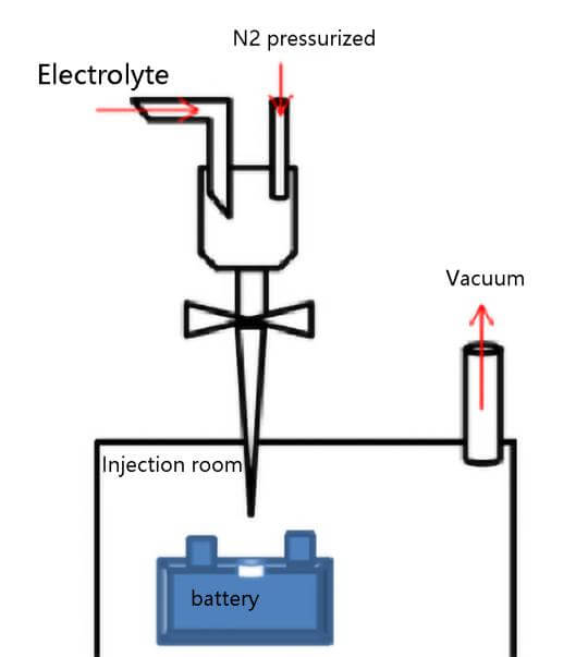
As shown in the figure, the electrolyte is injected into the sealed chamber through the quantitative pump, the battery is put into the liquid injection chamber, and then the vacuum pump evacuates the liquid injection chamber, and a vacuum environment is also formed inside the battery.
Then insert the injection nozzle into the battery injection port, open the electrolyte injection valve, and pressurize the electrolyte chamber with nitrogen to 0.2-1.0Mpa, keep the pressure for a certain period of time, and then vent the injection chamber to normal pressure.
Finally, let it stand for a long time (2-36h), so that the electrolyte can be fully infiltrated with the positive and negative materials of the battery and the diaphragm. When the injection is completed, the battery is sealed, and the electrolyte will theoretically penetrate into the diaphragm and electrodes from the top of the battery.
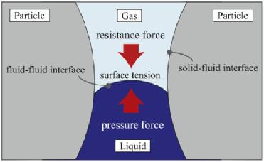
But in fact, a large amount of electrolyte flows down and collects at the bottom of the battery, and then penetrates into the pores of the diaphragm and electrode through capillary pressure, as shown in the figure.

Usually, the diaphragm is composed of a porous hydrophilic material, and the porosity is generally relatively large, while the electrode is composed of a porous medium composed of various particles. It is generally believed that the penetration rate of the electrolyte in the diaphragm is faster than that in the electrode, so the flow process of the electrolyte should first penetrate into the diaphragm and then penetrate into the electrode through the diaphragm, as shown in the figure.
As shown, the mechanism of electrolyte diffusion in the electrode pores can be seen as the interaction between three forces: the pressure Fl from the electrolyte flow, the capillary force due to the surface tension Fs, and the resistance due to the air in the pores Fg.
When injecting liquid, evacuating the battery can reduce the resistance generated by the air, and injecting the electrolyte under pressure can increase the driving force of the liquid flow. Therefore, the vacuum-pressurized injection is beneficial to the infiltration of the electrolyte.
During the first charge-discharge (pre-charge) process of the lithium ion battery, the electrolyte is reduced on the surface of the cathode, and the insoluble reduction product is deposited on the surface of the cathode material to form a passivation layer.
That is, the solid electrolyte interface film (SEI), this passivation film has the characteristics of solid electrolyte, is an insulator of electrons but an excellent conductor of Li+, and Li+ can be inserted and extracted freely through the passivation layer.
The voltage at which the SEI film begins to form is not fixed, it may be 2 V, 1 V or 0.8 V; moreover, the SEI film will be continuously formed during the charging and discharging cycles of the battery,
It is also related to many factors, such as anode material, electrolyte composition, additives, charging rate, temperature, etc. At the same time, the pre-charge reaction produces some gases such as ethylene, hydrogen, and carbon monoxide.
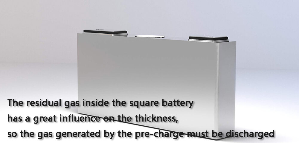
The residual gas inside the square battery has a great influence on the thickness, so the gas generated by the pre-charge must be discharged. There are generally two ways of pre-filling and exhausting: one way is to stick the liquid injection hole with adhesive tape and rubber sleeve cotton during the pre-filling process, and discharge the gas at one time during negative pressure sealing;
Another method is to open the injection hole during the pre-charging process to allow the gas to be discharged freely. This method has higher requirements on the ambient temperature and humidity, and requires a larger investment, but the process is relatively simple.
The closed-mouth process has a large airflow during sealing, which will flush out the electrolyte, and the amount of flushing out is uncontrollable. However, when the opening process is pre-filled, the gas is slowly discharged, and the electrolyte will not be brought out, and no electrolyte is discharged during the sealing process, and the consistency of the injection volume is good.
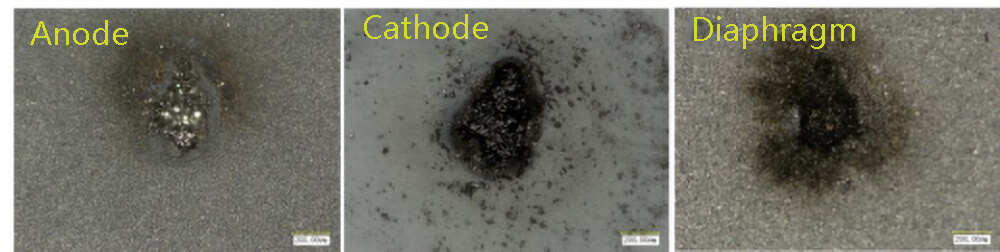
Charge the cell to full power, and observe the appearance of the battery lug piece after dissecting the cell. It is found that there are many stains on the surface of the closed process battery lug piece, and the surface of the open process battery lug piece is very clean. , lithium ions cannot pass through the bubbles, and uneven electrochemical reactions occur on the surface of the cathode sheet.
During the pre-charging process of the opening process, the bubbles are discharged, the lithium ions react uniformly on the surface of the cathode, the color of the surface of the electrode shows a good consistency, and the SEI film is formed relatively densely.
In order to improve the production efficiency of lithium-ion batteries, it is necessary to optimize the battery precharge current and time, so as to fully exhaust the gas in the battery in the shortest time. The pre-charge exhaust process is: pre-charge SOC is about 30% (0.2C, 1.5h), vacuum is 10min after pre-charge, and the vacuum degree is -96KPa.
Welding of injection port
Seal the opening of the battery injection port with glue nails, cover the aluminum injection plug, and then weld the injection plug to the top cover of the battery for sealing, so that the inside of the battery is completely sealed. The quality of welding is related to the sealing of the battery. Poor welding will lead to battery leakage, lithium precipitation, and poor battery appearance.
For the current laser sealing equipment, the CCD shooting effect and the welding waveform setting have a certain influence on the welding; the reasonable setting of the type of shielding gas and shielding gas parameters can improve the uniformity and width of the welding seam; Cleanliness, reducing the introduction of impurities and foreign matter, can effectively reduce the probability of welding slag.
In terms of mechanical fit, the clearance fit is better than the interference fit. The method of spot welding first and then continuous welding can largely solve the problem of warping during clearance fit; increasing the size control of the inclination angle of the injection hole concave platform can improve the welding penetration. The consistency of welding speed, output power and spot diameter are the main process parameters affecting welding strength.
Finally, the battery undergoes formation (the battery undergoes several complete charging and discharging procedures) and aging (storage at 4.0V state of charge at 45°C for 7 days, then 25°C for 2 days, and then sorted) to complete the manufacturing process.