Refresh

This website www.takomabattery.com/inverter-circuit/ is currently offline. Cloudflare's Always Online™ shows a snapshot of this web page from the Internet Archive's Wayback Machine. To check for the live version, click Refresh.

Inverter circuit - efficient designs for power conversion

Inverter circuit - efficient designs for power conversion

Inverter circuit is crucial for power conversion, specifically in converting DC (direct current) to AC (alternating current). Efficient designs of these circuits are essential for ensuring optimal performance and reliable power conversion. In order to get this efficient design when constructing an inverter circuit, you must consider several factors.

Efficient DC-to-AC converter circuits are vital for various industrial applications but also find extensive use in renewable energy systems, electric vehicles, uninterruptible power supplies (UPS), and many other areas. This post discusses the basis of inverter circuits and their design!

Table of Contents
youtube play button

What is the inverter circuit?

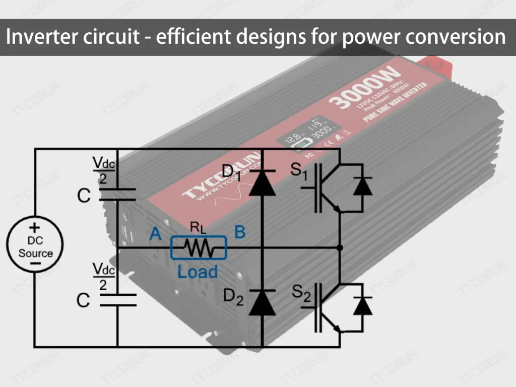
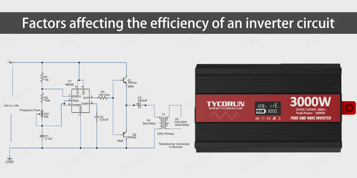
An inverter circuit is the circuitry or components that make up an inverter, allowing it to convert direct current, which flows in one direction (commonly provided by a battery), into alternating current, which changes direction often like the one in an outlet or generator. Building an inverter circuit involves a combination of different parts and techniques.

These consist of transistors, MOSFETs, transformers, microcontrollers, and oscillators. You can build an inverter circuit with careful design and implementation to satisfy particular needs and provide the best performance. The quality and complexity of the circuit will determine the output waveform, which may be square, modified sine, or pure sine.What is the inverter circuit

What uses inverter circuits?

There are several applications and disciplines for inverter circuits. A few of them are as follows:
  • This flexible inverter circuit may give backup power for appliances in the event of power outages or instability in the primary power source. This ensures that electrical gadgets that rely on AC power continuously operate perfectly.
  • By enabling users to power AC loads or feed the grid with renewable energy sources like solar or wind, it makes the adoption of sustainable energy practices easier. The main purpose of an inverter circuit is to convert a battery output to AC so that it may be utilized to power appliances at home or sold to the utility company.
  • The inverter circuit’s flexibility is seen by how it helps manage the speed and torque of AC motors, particularly those employed in industrial machinery or electric cars. This may increase the motor’s performance and efficiency while also reducing noise and wear.

How many types of inverter circuits are there?

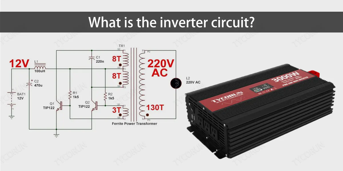
Inverter circuits are classed according to their output waveform, input source, output phase, commutation mechanism, connection type, mode of operation, number of voltage levels, and PWM approach. According to the output waveform, there are three main types of power inverter circuits:

  • Square wave inverter: This type of inverter produces a square wave output, which is a simple and low-cost option but is only suitable for some appliances due to potential noise, distortion, and overheating issues.
  • Sine wave inverter: The sine wave output produced by this kind of inverter is perfect for various appliances, simulating the utility supply for seamless and effective functioning. It is, therefore, also the most costly and sophisticated choice.Pure sine wave

There are two primary categories of power inverter circuits based on the input source:

  • Voltage source inverter (VSI): This form of inverter receives power from a DC voltage source, such as a battery or a solar panel. The output voltage is unaffected by the load, while the output current is affected by the load impedance. Changing the duty cycle or frequency of the switching devices may adjust the output voltage.
  • Current source inverter (CSI): This form of inverter gets its power from a DC source, such as an inductor or a current-fed converter. Like VSI, the output current is independent of the load, while the output voltage depends on the load impedance. Changing the firing angle or frequency of the switching devices may adjust the output current.

Inverter circuits may be broadly classified into two categories based on the output phase:

  • Single-phase inverter: Single-phase inverters are ideal for small-scale and home applications since they can convert DC input to single-phase AC output. Partially bridged and fully bridged are the two fundamental forms of single-phase inverter.
  • Three-phase inverter: This inverter type transforms direct current (DC) input into three-phase alternating current (AC), making it appropriate for industrial and large-scale applications. Three-phase inverters operate in two main modes: 180-degree and 120-degree.

How to design an inverter circuit?

The primary stages to construct a DC-to-AC converter circuit are as follows:
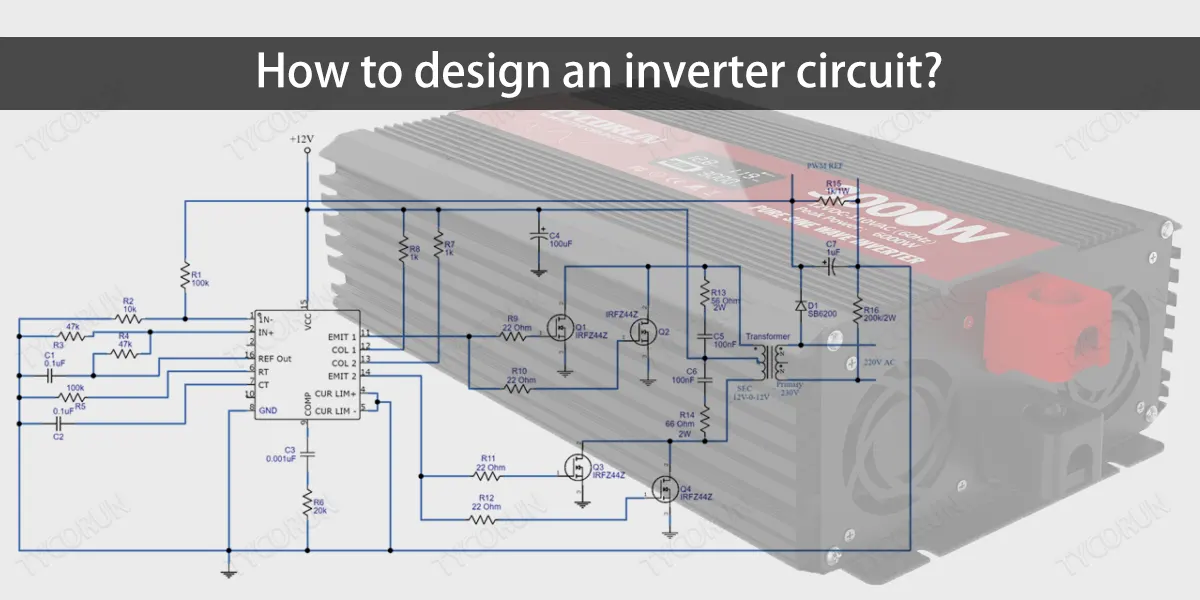
  • Step 1: Choose your inverter circuit’s input source, output waveform, output phase, and other details, including input and output voltages, frequencies, powers, and types of loads.
  • Step 2: Select the right parts and supplies for your inverter circuit, including a load, a commutating element, a transformer, a DC source, and a switching device. You can choose from the list of available parts, including diodes, capacitors, solar panels, batteries, transistors, MOSFETs, thyristors, inductors, resistors, and lights.
  • Step 3: Choose the appropriate inverter circuit type and configuration based on several parameters, such as the input source, output waveform, output phase, etc. You may employ other configurations, including 180-degree, 120-degree, half-bridge, full-bridge, series, and parallel.How to design an inverter circuit
  • Step 4: Sketch the circuit schematic for your inverter, representing the parts and connections using symbols and conventions. You may sketch and model your circuit using software such as LTSpice.
  • Step 5: Build a working prototype of your inverter circuit by assembling and testing it using a breadboard, wires, and tools. You may adhere to the schematic diagram and detailed instructions to connect the parts and ensure the circuit works.
  • Step 6: Assess the effectiveness and efficiency of your inverter circuit by confirming the output voltage, current, frequency, and power using calculations and measurements. Using a multimeter, oscilloscope, or power meter, you can measure the output parameters and compare them to the predicted values.

What are the key factors affecting the efficiency of an inverter circuit?

A power inverter circuit’s efficiency reveals how much DC power is transformed into AC power. One thing to consider is that some power may be lost as heat, while the inverter requires a certain amount of standby power to remain operational. Below are factors impacting a power inverter circuit’s efficiency.
 
The Type and Quality of the Switching Devices
These components, which include transistors, MOSFETs, thyristors, and IGBTs, are responsible for switching the DC input to AC output. They vary in terms of heat dissipation, switching loss, conduction loss, and switching speed.
 
The inverter circuit’s efficiency increases with the quality and loss of the switching components decreasing. A higher quality and reduced loss in the switching devices contribute to increased efficiency in the inverter circuit.
 
The Type and Quality of the Commutating Elements
These components (diodes, capacitors, inductors, or transformers) have various properties, including voltage drop, resistance, reactance, and leakage, and create a channel for the load current to flow while the switching devices are off. A power inverter circuit’s efficiency increases with improved quality and less commutating element loss.Factors affecting the efficiency of an inverter circuit
 
The Inverter Circuit’s Configuration
The inverter circuit’s configuration includes its series, parallel, half-bridge, full-bridge, 180-degree, and 120-degree modes. These configurations provide varying benefits and disadvantages regarding the output waveform, output phase, output voltage, output current, output frequency, and number of components. The input source, output load, and other parameters determine the ideal inverter circuit type and design.
 
Load Type and Size
The inverter circuit’s output voltage, current, frequency, and power—as well as its harmonics, distortion, and power factor—are all impacted differently by these load types, which include resistive, inductive, capacitive, and mixed. Since the efficiency of a power inverter circuit is often more significant at high output power and lower at low output power, the load size also impacts its output power and efficiency.
 
Environmental Conditions
Temperature, humidity, dust, and ventilation are a few environmental factors that may impact the reliability and efficiency of circuit components, such as heat dissipation, resistance, capacitance, and inductance.
 
Lower efficiency will arise at a higher temperature as component degradation and more losses occur. Because there will be less corrosion, pollution, and overheating, efficiency will increase with decreased humidity, dust, and ventilation levels.

What are some common issues with inverter circuits and how can they be resolved?

  • Overvoltage: When the DC input voltage is higher than the inverter’s rated value, it may cause overvoltage, which can harm components and cause a shutdown. You can fix this by increasing the deceleration time, using the “coast to stop” function whenever feasible, checking the supply voltage for persistent or brief high voltage, checking the brake chopper and resistor’s operation, installing a brake chopper and brake resistor in the inverter, or replacing the inverter with a regenerative drive.
  • Overcurrent: Overcurrent arises when the output current exceeds the inverter’s rated value, triggering overcurrent protection and resulting in a shutdown. To address this, inspect the load for short circuits, overloads, or ground faults, inspect the wiring for secure and accurate connections, confirm good output frequency and voltage settings, reduce acceleration and deceleration time, or upgrade to a larger-capacity inverter.
  • Overheating: This happens when the inverter or its components exceed the rated temperature, compromising performance and reliability and even resulting in a shutdown. Check the cooling fan for appropriate functioning, the ventilation for enough airflow, the ambient temperature for ideal circumstances, and the load for excessive or fluctuating power. Alternatively, replace the defective or damaged components to fix this problem.
  • Communication failure: An inverter’s inability to connect with the controller, interface board, or external devices may result in a communication failure, which can impair the inverter’s control and functionality and force it to shut down. In order to fix this problem, you can make sure that the communication cable is connected correctly, verify that the protocol and address are configured correctly, check the compatibility of the communication speed and format, verify that the communication devices are functional, or replace any broken or malfunctioning parts.

How can the performance of an inverter circuit be maintained?

You may adhere to the following advice to keep an inverter circuit operating at peak efficiency:
  • Keep the inverter circuit away from heat sources, fire, dust, moisture, and gas in a location with good ventilation. By doing this, fire dangers, corrosion, overheating, and contamination will be avoided.
  • Regularly clean the inverter circuit by wiping the outside with a moist cloth and the wires and connectors with a dry cloth. Water and chemicals should not be used since they may harm the electronics.
  • Verify that there are no loose or misplaced connections, overloads, short circuits, or ground problems in the wiring. Any damaged wires or parts should be tightened or replaced.
  • Track the output voltage, output current, output frequency, output power, and input voltage using the display or a multimeter to keep an eye on the inverter circuit’s performance. Search for any discrepancies or mistakes by comparing the data with the manufacturer’s specs.
  • Perform routine maintenance inspections, seeing a licensed electrician examine the internal parts, wiring, and connections. In addition to updating the firmware, replace any broken or deteriorated parts if required.

Conclusion

Inverter circuits are vital in various applications, including renewable energy systems. The goal is to design circuits that minimize losses and maximize the conversion efficiency. The article extensively discusses factors that affect a power inverter circuit design, as well as how to go about the design and maintain them. An adequately designed inverter circuit helps you use renewable energy to the fullest.

FAQs

The symbol for the power inverter circuit is a triangle with a circle at the output, representing the logical negation of the input. This symbol is also used for the NOT gate in logic design, as the image below illustrates.
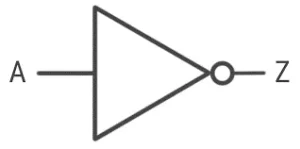
picture

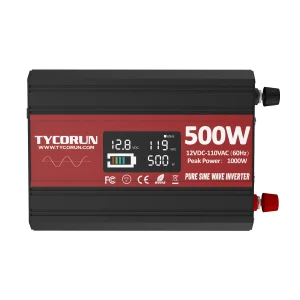
The voltage of a DC-to-AC converter circuit depends on input, output waveform, and circuit design. A simple example is a transistor-based inverter with 12V input and 6V square wave output.


The input voltage, output waveform, and circuit design all affect the inverter circuit's power output. In order to drive the output current, there must be sufficient input voltage. The output waveform has to be appropriate for the powered devices. The circuit design has to be secure, dependable, and effective.

Related products
Related posts

Leave a Comment

Your email address will not be published. Required fields are marked *

tycorun logo

TYCORUN ENERGY

We offer lithium ion battery products, solutions, and services across the entire energy value chain. We support our customers on their way to a more sustainable future.

Products

Recent Posts

Hot Posts

Contact Form Demo (#3)
Scroll to Top

Request A Quote

Email:info@takomabattery.com