Skip to content
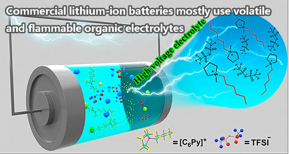
For a long time, most of the traditional commercial lithium-ion batteries use volatile and flammable organic electrolytes, which have a series of safety problems. Solid state electrolyte have attracted extensive attention due to their inherent high safety and good thermal stability. which battery has the most voltage with more security?
Among them, polymer electrolytes (SPE) have the advantages of flexibility, simple fabrication process, and good interfacial contact, but they also suffer from low ionic conductivity at room temperature, poor interface stability of positive and negative electrodes, and relatively narrow operating voltage window.
Dispersing active inorganic fillers in polymer matrices to form composite polymer electrolytes (CPEs) is beneficial for improving ionic conductivity and mechanical strength. In addition, the introduction of plasticizers can further improve the ionic conductivity of CPE.
However, the energy gap of a single CPE is still narrow and cannot expand the electrochemical window of the electrolyte. The construction of bilayer polymer electrolytes is expected to solve the above problems.
However, bilayer SPE causes additional polymer/polymer electrolyte interfacial resistance, low electrolyte interfacial compatibility, and discontinuous Li+ migration paths. Therefore, there is a need to design and construct bilayer SPEs with high ionic conductivity, low interfacial resistance, and strong oxidation resistance.
Introduction
A novel quasi-bilayer was proposed by adding plasticizers with high oxidation stability (propylene carbonate) and high reduction stability (diglyme) to polyvinylidene fluoride (PVDF)-based CPE Composite polymer electrolytes (QDL-CPEs).
In-situ polymerization of propylene carbonate can form a cathode electrolyte interface (CEI) film with enhanced antioxidant capacity. The nucleophilic substitution reaction between diglyme and PVDF increases the reduction stability of the electrolyte on the anode side and suppresses the formation of lithium dendrites.
QDL-CPEs possess high ionic conductivity, wide electrochemical window, stable electrode/electrolyte interface, and no additional electrolyte-electrolyte interface resistance. Therefore, QDL-CPE improves the cycling performance of NCM811//QDL-CPE// hard carbon full cells at room temperature.
QDL-CPE design and physical properties

Figure 1. a) Schematic diagram of the design strategy of QDL-CPE and PSSB; b-d) SEM images and e) ionic conductivity of QDL-CPE before and after aging. Figure 1a shows that, in order to satisfy both high voltage compatibility on the positive side and low negative reactivity on the negative side,
Different plasticizers PC and DGM were added to PLL-CPEs to obtain P-PLL-CPE and D-PLL-CPE to form QDL-CPE. Unlike conventional bilayer CPEs, QDL-CPEs are designed with the same basic composition except for the plasticizer, which can eliminate the contact interface of different electrolytes and thus avoid high interfacial resistance.
Therefore, based on the intermolecular interactions of PVDF, LLZO, LiTFSI, and PC or DGM, QDL-CPEs are expected to achieve high voltage compatibility, high ionic conductivity, and electrode/electrolyte interface stability on both cathodes and anodes.
Scanning electron microscopy (SEM) images revealed (Fig. 1b–d) that there was a visible polymer/polymer interface in the initial QDL-CPE compared to the single CPE. However, after aging, the visible interface in QDL-CPEs disappeared, implying almost no interface resistance in QDL-CPEs.
Furthermore, Figure 1e shows that, before aging, the single CPE shows higher ionic conductivity than the QDL-CPE due to the presence of the polymer/polymer interface in the QDL-CPE. After aging, they showed similar ionic conductivity, about 1.3 × 10⁻⁴ S cm-1 at room temperature, further confirming that there is almost no interfacial impedance between D-PLL-CPE and P-PLL-CPE in QDL-CPE.
Therefore, QDL-CPE can maintain high ionic conductivity, tight electrode-electrolyte interface, and is expected to possess unique interfacial electrochemical properties for positive and negative electrode applications.
Figure 2a–c shows that P-PLL-CPE is able to fully coat NCM811 particles and build a conformal coating to form an artificial CEI layer with a thickness of 15–30 nm. No voids were created between the artificial CEI layer and NCM811 (Fig. 2c), implying that it was stable during cycling with no contact loss.
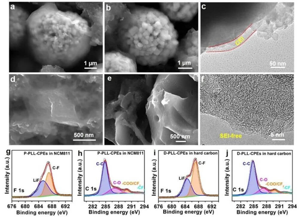
Figure 2, a, b) SEM images of NCM811 in P-PLL-CPE before and after 5 cycles; c) TEM images of NCM811 in P-PLL-CPE after 5 cycles;
d, e) SEM images of hard carbon in D-PLL-CPEs before and after 5 cycles;
f) HRTEM image of hard carbon in D-PLL-CPE after 5 cycles; NCM811 positive side of P-PLL-CPE
g) High-resolution XPS spectra of F1s and h) C1s; i) High-resolution XPS spectra of F1s and j) C1s of D-PLL-CPE on the hard carbon anode side.
For the negative side, the lithium negative electrode is replaced by hard carbon due to the instability of lithium metal. Figure 2d shows that the hard carbon is covered with a layer of D-PLL-CPE, indicating that the hard carbon has good compatibility with D-PLL-CPE.
SEM and high-resolution transmission electron microscopy (HRTEM) images (Fig. 2e, 2f) show that the D-PLL-CPE layer on the hard carbon disappears after cycling, indicating that there is no passivation layer on the anode side, which would facilitate the transport of lithium ions .
Furthermore, XPS revealed that LiF was formed in situ in the PVDF-based electrolyte (Fig. 2g–j). The pre-formed LiF is dispersed in the electrolyte, a space charge layer of the Li+ conductor, which facilitates ion transport (Figures 2g and 2i). Figures 2h and 2j show that the signal of C1s remained largely unchanged after cycling, indicating that the formation of LiF did not affect the stability of the polymer.
Analysis of electrolyte bonding and redox properties
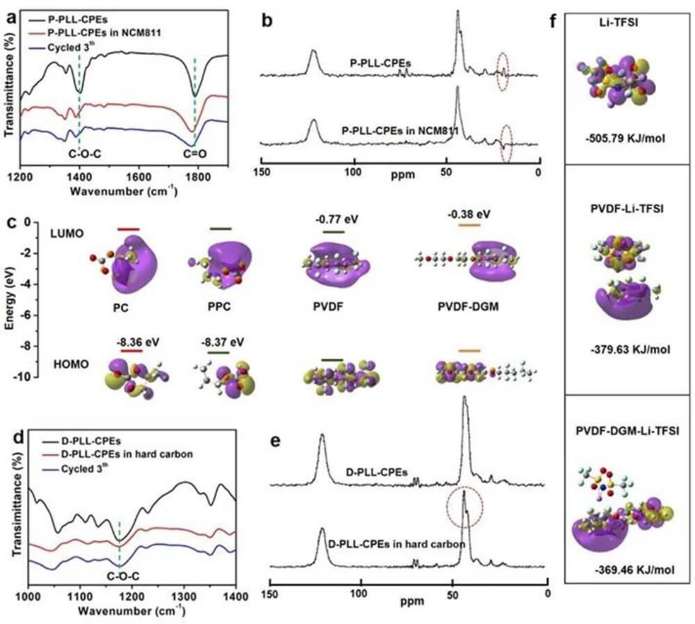
Figure 3. a) FTIR spectrum and b) SSNMR spectrum of P-PLL-CPE; c) HOMO and LUMO energy levels of electrolyte components calculated based on density functional theory (DFT); d) FTIR spectrum of D-PLL-CPE and e) SSNMR spectra; f) comparison of dissociation and adsorption energies.
To gain insight into the intermolecular interactions in electrolytes, P-PLL-CPEs and D-PLL-CPEs were characterized by Fourier transform infrared spectroscopy (FTIR) and solid-state nuclear magnetic resonance (SSNMR).
Figure 3a shows that the peaks at 1400 and 1790 cm-1 are attributed to the C-O-C and C=O vibrations of PC in P-PLL-CPE. It shifted to lower wavenumbers after mixing with NCM811, indicating that PC aggregated into PPC on the surface of NCM811.
This was further confirmed by 13C in SSNMR (Fig. 3b). The peak at 19 ppm was attributed to the PC plasticizer in P-PLL-CPE, and when mixed with NCM811, the peak shifted to a low angle, indicating ring-opening polymerization of PC.
When PC is polymerized into PPC, the decrease in HOMO orbital energy indicates that the oxidative stability is improved (Fig. 3c), which is more beneficial to protect the cathode material in the charged state.
During the preparation of D-PLL-CPE, the C-O-C vibrations in DGM (Fig. 3d) were shifted from 1100 cm-1 to 1175 cm-1, indicating a nucleophilic substitution reaction between DGM and PVDF.
Furthermore, in the SSNMR spectrum, the C–H peak at 44 ppm in PVDF was clearly split, indicating that DGM was connected to the C–H bond of PVDF (Fig. 3e). After mixing D-PLL-CPE with hard carbon, the copolymer (PVDF-DGM) showed no structural change, even after cycling (Fig. 3b).
After the hydrogen in PVDF was replaced by DGM, the LUMO changed from -0.77 eV to -0.38 eV, which improved the reduction stability of D-PLL-CPEs (Fig. 3c).
In addition, the adsorption energy of PVDF-DGM for Li+ (-379.63 KJ/mol) is higher than that of PVDF for Li+ (-369.46 KJ/mol) (Fig. 3f), indicating that PVDF-DGM is more favorable for the dissociation of LiTFSI, thereby Enhanced Li+ transport.
In situ electrochemical confocal system testing
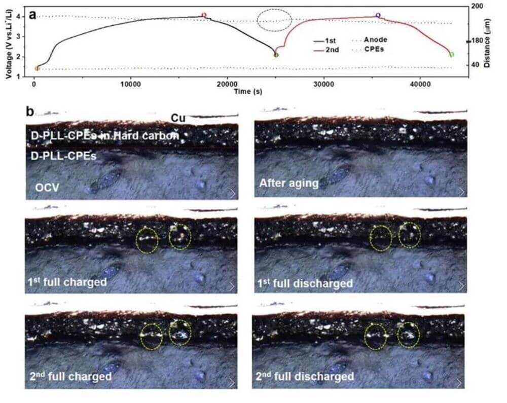
Figure 4. a) Charge-discharge curves and volume changes during cycling; b) Photographs at different charge-discharge states.
Li dendrite growth on the anode/electrolyte interface and changes in electrode expansion and contraction during cycling can damage the electrode-electrolyte interface and lead to poor electrochemical performance of the battery.
Therefore, in situ ECCS characterization was employed to investigate the structural and chemical stability of the D-PLL-CPE/hard carbon interface. Figure 4a shows that, based on the intercalation mechanism, hard carbon has almost no volume expansion. D-PLL-CPEs contract when charged and expand when discharged.
Figure 4b shows that a tight D-PLL-CPE/hard carbon interface can be observed before and after aging. After Li+ insertion, the hard carbon region turns yellow. When the Li+ is released, the color gradually returns to its previous state.
However, the inserted Li+ cannot be fully extracted, resulting in a loss of Coulombic efficiency (CE). However, at the interface between hard carbon and D-PLL-CPE, no lithium dendrites formed. The stable and compact D-PLL-CPEs/hard carbon interface can reduce the local potential and thus avoid the formation of Li dendrites.
Furthermore, no contact failures were found in the D-PLL-CPEs/hard carbon interface, which would contribute to the excellent rate performance and cycling stability.
Electrochemical properties of PSSB
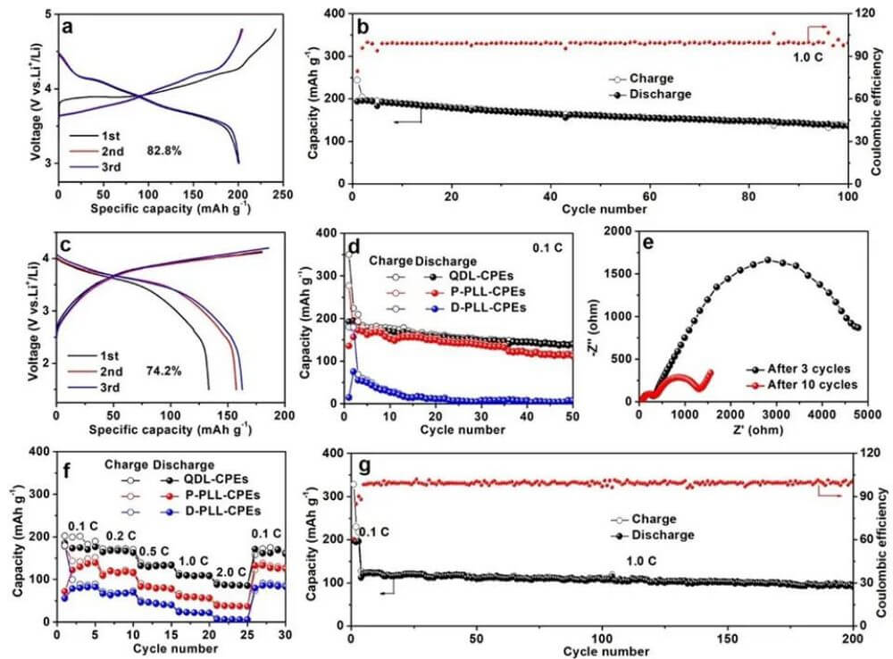
Figure 5. NCM811//QDL-CPEs//Li
a)charge-discharge curve and b) cycle performance at 1 C; c) The charge-discharge curve of NCM811//QDL-CPEs//hard carbon; d) Cycling performance of PSSB based on different electrolytes; e) EIS spectra of NCM811//QDL-CPEs//hard carbon under different cycles; f) PSSB rate performance based on different electrolytes; g) Long-cycle performance of NCM811//QDL-CPEs//hard carbon at 1 C.
Figure 5a-b shows that NCM811//QDL-CPEs//Li cells exhibit a high initial coulombic efficiency (ICE) of 82.8% in the voltage range of 3–4.8 V when the high-voltage NCM811 cathode is matched with the Li metal anode. .
The specific capacity of 136.5 mAh g-1 was maintained after 100 cycles without the formation of lithium dendrites, indicating that the QDL-CPE possesses high oxidation resistance, wide electrochemical window and stable interfacial properties.
Figure 5c shows that the ICE of NCM811//QDL-CPEs// hard carbon cells is 74.2%. Furthermore, compared with pure P-PPL-CPE and D-PPL-CPE cells. The QDL-CPE battery has higher capacity and longer cycle stability (Fig. 5d), indicating that QDL-CPE can meet different requirements for positive and negative interface properties.
Figure 5e shows that the charge transfer resistance (Rct) becomes smaller after multiple cycles, but the interface resistance (Rf) remains almost unchanged. This means that the CEI is stable, no new passivation layer is formed during cycling, and there is no structural change in the electrode material.
Smaller Rct will be beneficial to improve the magnification performance. The capacities of NCM811//QDL-CPEs// hard carbon cells at 0.1, 0.2, 0.5, 1 and 2 C are 174.6, 167.4, 132.1, 109.2 and 87.9 mAh g-1, respectively. When the current density was restored to 0.1 C, the capacity was restored to 170.1 mAh g-1 (Fig. 5f). Even at 1 C, there is still a capacity retention of 80.2% after 200 cycles (Fig. 5g).

Summary and outlook
In this paper, a new concept of QDL-CPE is proposed by introducing different kinds of plasticizers PC and DGM into PVDF/LLZO/LiTFSI CPE. In QDL-CPE, there is no additional electrolyte-electrolyte interfacial resistance, and high ionic conductivity, wide electrochemical window, and interfacial stability can be simultaneously achieved.
The bilayer electrolyte enables the formation of different interfaces on the positive and negative electrodes, in which a stable CEI-like layer can be obtained on the positive side of NCM811, while no SEI is present on the hard carbon negative electrode. In addition, no lithium dendrites were formed during cycling.
Second, the in situ polymerization of PC can enhance the antioxidant stability of P-PLL-CPEs, while the nucleophilic substitution reaction of DGM and PVDF can improve the low-voltage stability of D-PLL-CPEs.
Finally, PVDF-DGM is more conducive to the dissociation of lithium salts and facilitates the transport of Li+. All these advantages enhance the electrochemical performance of NCM811//QDL-CPEs//hard carbon full cells at room temperature. Finally, if you want to know about the solid-state battery industry information, you can refer to Top 10 solid-state battery companies in 2022.