- Related background
- Battery requirements for solid state electrolyte
- Mechanical properties of solid state electrolyte
- Source of electrochemical-mechanical effects
- Electrode challenges
- Layering of active materials and solid state electrolyte
- The challenge of the battery stack
- Operation under mild pressure-charge transport in electrodes
- Conclusion and outlook
Related background
All solid stated battery using inorganic solid state electrolyte have been the focus of next-generation energy storage devices due to their potential for high energy density and excellent safety, You can learn about related information from the energy density of lithium ion battery mentioned earlier. Recent advances in this field are mainly based on material advancements, such as the discovery of solid state electrolyte with high ionic conductivity and improved interfacial stability of electrodes.
However, the use of inelastic SE can lead to severe electrochemical-mechanical failures such as cathodic active material (CAM) disintegration, CAM/SE contact loss. As well as the stress accumulation during cycling, the Li+ and e- transport pathways are deteriorated.
The mechanical properties of solid state electrolyte are a key factor in the development of practical all-solid-state batteries (ASSBs), as they affect the effective contact area between solid state electrolyte and active materials, and in turn, the fabrication methods of electrodes.
For example, the application of “brittle” oxide solid state electrolyte has been very complicated because they cannot make good ionic contact with CAMs without the help of liquid or polymer electrolytes.In contrast, thick composite electrodes with high mass loadings can be fabricated by employing plastic solid state electrolyte (i.e., sulfides and polymers), providing high initial areal capacities comparable to their LE counterparts. However, the intrinsic properties of inorganic solids, namely transfer and absorption of external stress, have important electrochemical-mechanical effects on the performance of ASSBs.
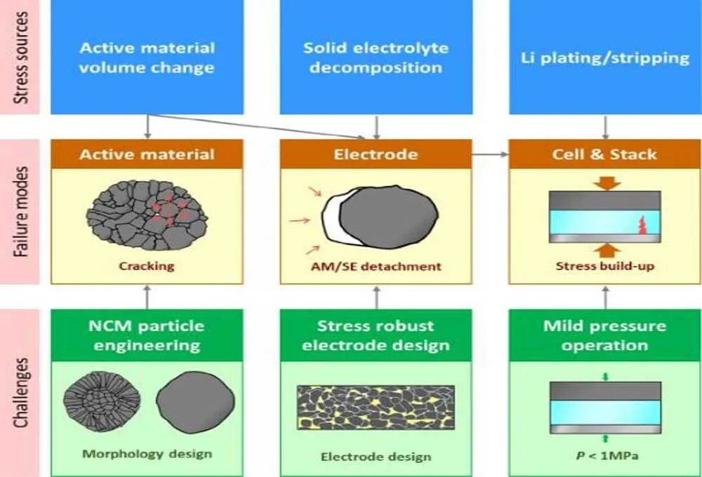
Figure 1. Classification of stressors, possible chemical-mechanical failure modes, and challenges to ASSB.
Clearly, the actual behavior of ASSBs is more complex than what we discuss here because of the irregular distribution of solid state electrolyte and pores in the cell.
The main stressor of ASSBs is the volume change of the active material upon cycling. First, this creates internal microcracks within the CAM particles. The accumulation of these microcracks eventually leads to the “disintegration of the CAM particles.
Even under high external pressures of tens of MPa (MPa), the internal cracks are not absorbed by SE. This is in stark contrast to LIB, where LEs penetrate into cracks and, upon cycling, the active contact area increases. Second, the repeated volume expansion/contraction of the active material cannot be easily accommodated by the deformation of the SE, which leads to the “detachment” of the SE from the active material, and thus the effective contact area of the CAM/SE is reduced.
Furthermore, in a recent study, careful observation of the initial charging phase revealed that the redox reaction of solid state electrolyte induces local stress in the composite electrode. These two stressors, i.e., active materials and solid state electrolyte, jointly caused the electrochemical-mechanical failure of the composite electrode.
Battery requirements for solid state electrolyte
For advanced ASSB technology, solid state electrolyte should meet multiple requirements, including high ionic conductivity, wide electrochemical stability window, chemical stability to ambient air, thermal stability, and mechanical properties.

Figure 2. (a) Comparison of various SE compounds for ASSB application requirements. (b) Comparison of the electrochemical stability windows of inorganic solid state electrolyte. The upper and lower limit potentials were estimated by DFT calculations. (c) Typical stress-strain curves for brittle and ductile materials.
The performance characteristics of the four main solid state electrolyte are compared in the picture: oxide, sulfide, chloride, and polymer electrolyte. Among them, high ionic conductivity comparable to LEs is a prerequisite for operable ASSBs at room temperature.
The oxide SE exhibits moderate ionic conductivity at room temperature, approximately 10-6-10-3 S cm-1. Solid polymer electrolytes (SPEs), in which lithium salts are dissolved into the polymer matrix, show very low ionic conductivity (10-8-10-7 S cm-1 at room temperature).
The addition of oxide ceramics to SPE to form composite polymer electrolytes (CPEs) can significantly improve the ionic conductivity, which can be attributed to the reduced crystallinity of polymer domains, interfacial conduction effects, and the contribution of oxide solid state electrolyte.
However, their maximum ionic conductivities are two orders of magnitude lower than LEs (∼10-2 S cm-1). In contrast, recent searches for sulfide and halide solid state electrolyte have yielded high ionic conductivities, reaching maxima around 10-2 and 10-3 S cm-1, respectively.
The chemical stability of SE under humid conditions is important for reliable and cost-effective battery production. Although oxide solid state electrolyte are not affected by complete hydrolysis, their surface degradation severely hinders the interfacial transfer of Li+. Sulfide SE is highly sensitive to humidity and produces toxic H2S gas.
The feasible operating voltage of ASSB is constrained by the electrochemical stability of SE. Polyethylene oxide (PEO)-based SPEs start to be oxidized at 4.0V (vs. Li/Li+), which leads to high interfacial resistance when combined with 4V-grade CAMs such as LiCoO2.
This interfacial degradation problem is solved by introducing surface coatings such as Li3PO4, Al2O3, and poly(ethylcyanoacrlate) (PECA). It is predicted that the electrochemical oxidation stability of inorganic materials is determined by the anion species, indicating that the anion is the center of oxidative decomposition (Fig. 2b).
From the upper voltage limit, the order of intrinsic electrochemical oxidation stability is: fluoride > chloride > bromide ≅ oxide > sulfide ≅ iodide. Sulfide solid state electrolyte show a very narrow stability limit, around 2.5 V (vs. Li/Li+). The oxidative stability of oxides is mainly affected by metal ions.
Importantly, the chloride SE is predicted to be stable to 4.3V (vs. Li/Li+), which renders the protective layer on the 4V-level layered oxide CAM non-existent. Notably, fluoride exhibits particularly high oxidative stability (>6 V vs. Li/Li+), which is offset by its low ionic conductivity.
This is due to the small ionic size and high electronegativity (and thus low polarizability) of F-. Importantly, the electrochemical decomposition of SE has been extensively studied with the formation of resistive decomposition products at the interface, which explains the actual electrochemical window.
Mechanical properties of solid state electrolyte
In general, oxides and polymeric solid state electrolyte are considered as brittle and ductile materials, respectively. Brittle materials tend to have high elastic moduli (E), with a few exceptions, such as the brittle-to-ductile transition of yttrium-stabilized zirconia, and the low elastic moduli of still brittle ceramic aerosols. Furthermore, elastic modulus and ductility are largely affected by grain size, porosity and dislocation distribution.
Brittle materials show less dimensional change than ductile materials when the same mechanical stress is applied. When the elastic strain limit is exceeded, brittle materials undergo brief plastic deformation followed by fracture. In contrast, the dimensions of ductile materials change through plastic deformation.
Representative strain-stress curves for different materials are shown in Figure 2c. Shear modulus (G) and bulk modulus (K) represent the resistance of a material to shear deformation and hydrostatic compression, respectively.
Poisson’s ratio (ν) is the ratio of lateral and axial strain and an important parameter describing the compressibility of a material (i.e. ν=0 for a fully compressible material and ν=0.5 for an incompressible material).
Mechanical Properties of Inorganic SE

The mechanical parameters of the main inorganic solid state electrolyte are listed in Table 1. Oxides are brittle compared to other compounds. However, exceptionally, several glass oxide solid state electrolyte can be deformed by cold pressing to form two-dimensional (2D) contacts with CAMs (90Li3BO3-10Li2SO4: 1.0 × 10⁻⁵ S cm-1 and 42Li2SO4-28Li2CO3-30LiI: 5.9 × 10⁻⁶ S cm-1/25°C).
Due to its low elastic modulus value, sulfide SE is considered to be one of the most ductile inorganic solid state electrolyte (for example, β-Li3PS4: 29.5 GPa, 75Li2S-25P2S5: 23 GPa, Li7P3S11: 21.9 GPa, and Li6PS5Cl: 22.1 GPa ).
In particular, sulfide solid state electrolyte in glassy morphology are known to be more easily deformable than their crystalline counterparts. The Li2S-25P2S5 glass becomes softer as it accommodates the softer I- and Br- ions. This is because the incorporation of larger anions reduces the ion packing density and increases the lattice polarizability.
The emerging halide solid state electrolyte are another class of ductile solid state electrolyte. Recent DFT calculations show that chloride solid state electrolyte are less deformable than sulfides, but bromide solid state electrolyte show comparable deformability.
The fabrication scheme of ASSB cells is highly dependent on the mechanical properties of SE. Layered NCM or Li[Ni,Co,Al]O2 (NCA) are indispensable CAMs for ASSBs. Because they are brittle oxides, oxide solid state electrolyte cannot form 2D contacts with them by simple pressing methods.
Furthermore, the thermal sintering process is problematic because it causes unwanted interfacial side reactions. The most traditional way to integrate oxide solid state electrolyte is to fabricate thin-film ASSBs, which is difficult for mass production targeting large-scale applications such as electric vehicles.
Another common practice for tailoring ASSBs using oxide solid state electrolyte is to use LEs and/or polymer electrolytes for mixing. In contrast, the deformable mechanical properties (5 < E < 12 GPa) of sulfide solid state electrolyte allow them to be easily integrated into the assembly of ASSBs by a cold pressing method, which is also the case for halide and hydride solid state electrolyte.
Mechanical properties also affect the dimensional controllability of the ceramic. Ceder and colleagues proposed a quantitative model to determine the effective particle size ratio of CAM to SE. They suggest that the particle size of SE should be small enough to fully utilize the capacity. For example, when the weight ratio of CAM to SE is 75:25, the particle size ratio of CAM to SE is estimated to be 2.1, and the CAM utilization rate is 98%. Nonetheless, smaller CAM particle sizes are also required in order to build electron pathways and reduce the diffusion length inside the CAM particles. J
Anek and co-workers report that LiNi0.6Co0.2Mn0.2 particles with an average particle size (D50) of 4.0 μm outperform those with larger D50s (15.6 and 8.3 μm), suggesting that the optimal particle size of SE is less than 1.9 μm. It will decrease further as higher energy densities require higher CAM-to-weight ratios. The particle size of brittle “oxides” can be reduced to less than 100 nanometers by simple mechanical pulverization, such as ball milling and jet milling.
However, pulverized sulfide solid state electrolyte with D50 < 1 μm are rare so far. This large difference in particle size between oxides and sulfide solid state electrolyte is related to their different responses to mechanical collisions that occur during pulverization and reflects the fact that oxides and sulfides experience brittle and ductile fractures, respectively. It should be noted that most sulfide solid state electrolyte with high ionic conductivity (for example, >1 mS cm-1 at 25 °C) can be synthesized at temperatures high enough to induce particle growth (>450 °C). Therefore, considering the ductility of SE, it is very necessary to develop a scalable particle size reduction method.
Recently, Janek and colleagues demonstrated that the ductility of sulfide solid state electrolyte (β-Li3PS4 and Li6PS5Cl) is affected by crystallinity, resulting in different cycling performances.
Likewise, Li2S-P2S5-LiI glass with improved formability exhibits better cycle retention than Li2S-P2S5 glass when used in silicon composite electrodes.
The brittleness of SE increases with increasing crystallinity. Monroe and Newman proposed that dendritic Li growth due to coarsening of the SE|Li interface can be suppressed when the shear modulus of the SE layer is higher than 8.5 GPa.
Overall, the mechanical properties of inorganic solid state electrolyte affect the fabrication method of ASSBs, the particle size controllability of solid state electrolyte, and the electrochemical-mechanical behavior of ASSSBs during cycling.
Source of electrochemical-mechanical effects
Volume change of active material
The volume change and spatial strain distribution of active materials during cycling is an important issue for conventional LIBs.
Reaction equations and corresponding theoretical capacity and volume changes of active materials for lithium batteries

Decomposition of solid state electrolyte
The electrochemical degradation of SE and its effect on the performance of ASSBs have been intensively studied in the formation of resistive layers and the interdiffusion of metal ions. Recent studies have found that the electrochemical degradation of SE is also an important source of electrochemical-mechanical effects.
Although its effect on the total packing pressure is often arguably insignificant compared to the volume change of the active material, it should be noted that the resulting stress occurs in a highly localized manner.
Jung and his colleagues performed a poorly operable electrochemical stress measurement (DEP) study comparing the electrochemical and mechanical effects of employing LiI-Li3PS4 and Li10GeP2S12 in graphite electrodes.
Li10GeP2S12 is unstable at potentials below about 0.6 V (vs. Li/Li+), and its decomposition reaction easily propagates to bulk SE particles due to the electronically conductive properties of its reduction products (e.g., Li3P, LixGe).
This interfacial stress is translated into a significant increase in the internal cell pressure, which is comparable to the pressure originating from Li+ intercalation into graphite (Fig. 3b). Li and his colleagues proposed that the electrochemical stability of SE is affected by mechanical shrinkage.
Computational simulations show that the electrochemical window of Li10GeP2S12 expands from 1.75 to 2.2 V to approximately 0.5–2.5 V as the pressure increases from 0 to 20 GPa. They explain these transferable phenomena by the restricted expansion tendency of ceramic sulfides during decomposition under mechanical constraints.
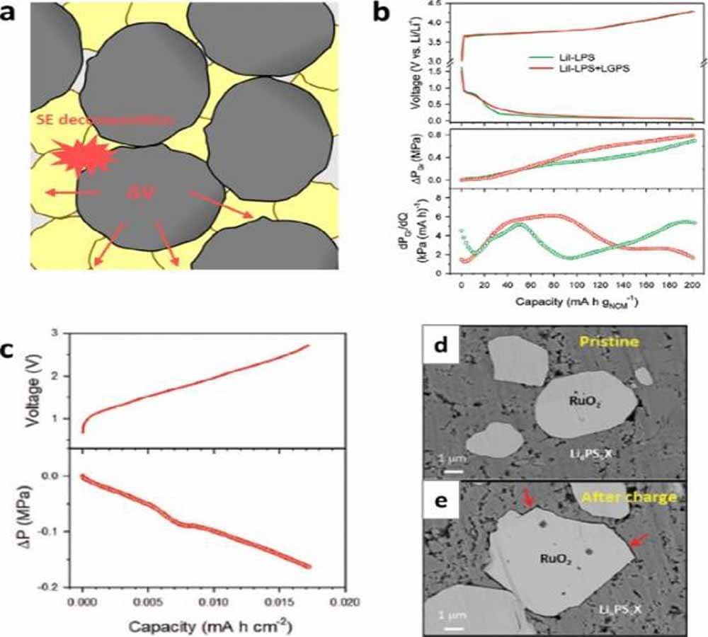
Figure 3. (a) Stressors during ASSB cycling. (b) SE, lithiation voltage curves, ΔPGr and dPGr/dQ of NCM|graphite cells using only LiI-Li3PS4 (LiI-LPS) or LiI-LPS and Li10GeP2S12 (LGPS) as graphite electrodes. (c) DEP results of RuO2|LTO cell. Cross-sectional SEM images of the RuO2/LPSX composite electrode (d) before cycling and (e) after charging.
Electrode challenges
Decomposition of CAMs
The use of Ni-rich CAMs for ASSB is essential because they contain less expensive Co and exhibit higher reversible capacity than LiCoO2.
Although lithium cobaltate is readily prepared as monocrystalline (monolithic) particles, most of the commercially available NCM particles display polycrystalline morphology, in which randomly oriented primary particles are in close contact with each other (Fig. 4a).
This morphological feature triggers a major electrochemical-mechanical failure of intergranular microcracks. This is mainly caused by the anisotropic volume change of the CAM crystal (i.e. expansion along the c-axis during delithiation and contraction at the a-b plane).
This anisotropic change in unit cell parameters becomes more pronounced with increasing nickel content in NCM or NCA, as the ionic size of nickel ions changes the most. In addition, the absolute volume change after charging also increases.
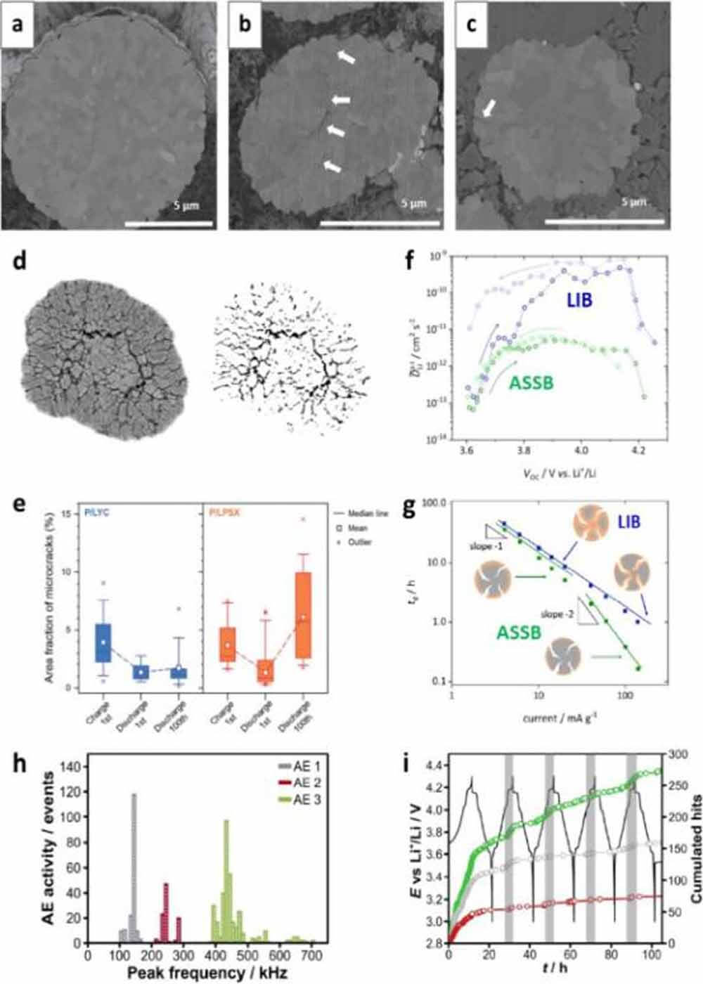
Figure 4. Cross-sectional images of polycrystalline NCM particles in (a) pristine state, (b) after charging with LE, and (c) after charging with SE. (d) Exemplary image processing for quantification of CAM cracks; (e) results comparing CAMs using sulfide SE and chloride SE. (f) Apparent Li+ diffusion coefficient measured by GITT under semi-infinite boundary conditions. (g) Comparison of discharge time (td) and ESD current graphs for LIB and ASSB. (h) Cumulative acoustic emission (AE) activity measured during the first five cycles of LIB. (i) Battery voltage and corresponding cumulative CTR for different frequency bands.
For liquid Li-ion batteries, LEs infiltrate NCM particles through intergranular microcracks or nanocracks. In addition to this liquid flooding, the electrochemical reaction of LEs on the disclosed particle surfaces accelerated the disintegration of CAM particles.
As a result, large cracks were created on the CAM particles (Fig. 4b). Nonetheless, as long as a sufficient number of LEs are provided, LEs can wet any exposed particle surface to generate electrochemically active interfaces. This increases the active surface area for Li+ transfer.
For ASSB, SE cannot flow into the cracks; the cracks remain voids that hinder the diffusion of intergranular Li+ (Fig. 4c). Ultimately, the repeated internal cracks lead to the isolation of the CAM crystals (Fig. 4d), which is responsible for the initial coulombic inefficiency and rapid capacity decay.
Quantification of internal cracks can be performed by cross-sectional image analysis, estimation of apparent chemical diffusion coefficients, and acoustic emission measurements. Figures 4d and e show an exemplary image analysis estimating the area fraction of internal voids evolved from fracture accumulation. In this in situ analysis, the crack area fraction of charged Li0.88Co0.11Al0.01O2 was estimated to be 3.69% for electrodes using Li6PS5X (LPSX).
In the subsequent full discharge, the proportion of cracks decreased to 0.90% with the enlargement of the grains. However, after the 100th cycle, the cracked fraction was as high as 6.14%, even in the discharge state, implying the accumulation of internal cracks upon cycling (Fig. 4e).
Janek and colleagues used electrochemical methods to study the effect of microcracks on LIB and ASSB dynamics. The apparent chemical diffusion coefficients of cells using sulfide SE and organic LE were measured to be in the same range when both cells were charged to 3.75 V (compared to Li/Li+) (Fig. 4f).
However, at higher voltages, the cells using organic LEs showed a dramatic increase in the chemical diffusion coefficient compared to those using sulfide solid state electrolyte. Because the chemical diffusivity is an inherent property of a material, this difference is caused by the increased contact area of the CAM and LE with internal cracks. It also shows that the microcracking of Ni-rich layered oxides is severe when charged above about 4.0 V (vs. Li/Li+), where H2-H3 transformation occurs. They also measured the relationship between discharge time (td) and discharge current to estimate the kinetic boundaries of each system (Fig. 4g).
In a logarithmic plot of td versus current, the slope is expected to be -1 for finite diffusion and -2 for semi-infinite diffusion. In contrast to batteries using organic LEs, solid-state batteries exhibit semi-infinite diffusion behavior in the increased current range, implying that full utilization of CAM is not possible in this kinetic environment.
In contrast, operational detection of CAM cleavage is very useful for battery diagnostics under realistic operating conditions and during long-term cycling, which is sorely lacking for ASSBs. An applicable technique is acoustic emission measurement, which is frequently used for LIB diagnosis (Fig. 4i).
For LIBs using LEs, the electrochemical-mechanical failure of CAMs can be mitigated by using compositionally graded CAM particles, refining particle size, and designing mechanically compliant morphologies. Dahn and his colleagues demonstrated that single-crystal NCM∣graphite cells can provide excellent cycle life (~4% capacity loss after 4000 cycles).
This exceptional cycling capability is attributed to the mechanical robustness of single-crystal NCMs, which results in fewer microcracks and thus reduced LE decomposition of newly exposed internal interfaces. Sun and his colleagues synthesized NCMs with radially oriented primary particles, where the (003) plane is energetically stable and thus circumferentially aligned.
This crystallographic texture transforms the random strain distribution into a uniform circumferential strain distribution, which effectively suppresses local stress concentration and thus microcracks during cycling. These morphological solutions for electrochemical-mechanical failure also work well for ASSBs.
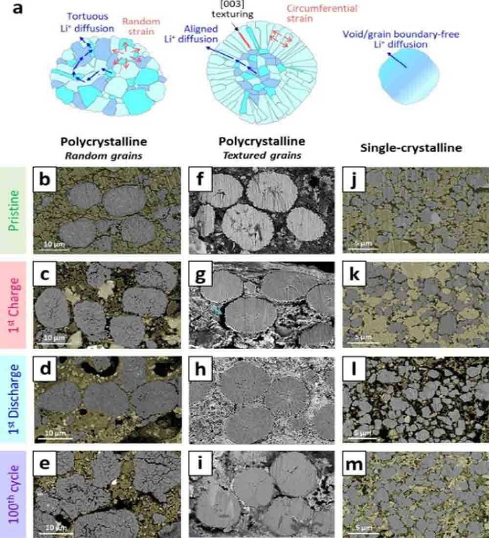
Figure 5. (a) Schematic representation of the microstructural morphology showing the localized stress directions and Li+ diffusion pathways for polycrystalline CAM grains with randomly oriented grains, textured (radially oriented rod-like) grains, and single crystalline CAM grains.
Figure 5a illustrates three CAM particle morphologies: polycrystalline with i) randomly oriented primary particles, ii) radially oriented rod-like primary particles, and iii) void-free monolithic particles (single crystals). The polycrystalline CAM with randomly oriented grains showed severe intergranular microcracks even after initial charging (Fig. 5c).
After the subsequent discharge, the volume fraction of internal cracks decreased, but the intergranular contact was not fully recovered (Fig. 5d). After 100 cycles, the pristine CAM particle structure was destroyed, while microcracks in the primary particles were also observed (Fig. 5e), which was responsible for the severe capacity loss after cycling (Fig. 6a).
In contrast, CAMs with crystallographic texture showed marginal internal cracks (Fig. 5f–i). The single-crystal CAMs are also mechanically robust against internal stress build-up upon cycling (Fig. 5j–m).
In addition to the mechanical properties of the CAM, other factors can also affect the degree of CAM disintegration. Under a given externally applied build-up pressure, the internally generated stress is accumulated, and the degree of stress relaxation and the resulting stress distribution largely affects the cracking behavior of the CAM.
Jung and co-workers showed that the cycling performance of ASSB is severely affected by the volume fraction of SE, even when using electrochemically stable Li3YCl6 and mechanically compliant single-crystal CAM. The composite electrode containing 40.7 wt% SE exhibited better capacity retention than that containing 29.1 wt% SE (Fig. 6d).
The Li diffusion behavior in CAM particles is also affected by its morphological characteristics, especially for ASSB applications. For LIBs using LEs, the LEs can infiltrate through cracks and wetting the internal grains, resulting in the diffusion of Li+ out.
In contrast, for ASSB, Li+ diffuses only through selected grain boundaries, connecting the active planes for Li+ transfer [see (003) plane]. Therefore, in polycrystalline CAMs with random orientations, the diffusion pathway of Li+ is very tortuous, hindering the rapid (de)intercalation of Li+ (Fig. 5a).
The crystal-textured CAMs possess highly aligned Li+ diffusion pathways (Fig. 5a). The void-free character of single-crystal CAM is also beneficial to minimize the tortuosity of internal Li+ diffusion (Fig. 5a), as the apparent Li+ chemical diffusion coefficient of single-crystal CAM is improved compared to that of polycrystalline CAM (Fig. 6e) .
Figure 6. (a) Cycling performance of ASSB using polycrystalline CAM particles with random orientation and texture. . Cross-sectional SEM images of composite electrodes using Li3YCl6 as SE with weight fractions of (b) 29.1% and (c) 40.7%, and (d) their corresponding cycling performance compared to LE cells. (e) Comparison of apparent Li+ diffusion coefficients for composite electrodes using single- and polycrystalline CAMs.
Layering of active materials and solid state electrolyte
The flow of LE can keep up with the volume change of the CAM, thereby maintaining the CAM/solid state electrolyte contact. On the contrary, due to the inelastic character of SE, the CAM/SE contact is severely damaged upon cycling. In particular, there is a large amount of CAM/SE exfoliation during the charging process, during which the lattice volume of the CAMs shrinks. Figure 7a and b show cross-sectional scanning electron microscopy (SEM) images of the NCM composite electrode before and after initial charging (delithiation). In addition to the internal cracking of the CAM, severe delamination of the CAM and SE was also observed. This delamination reduces the ion contact area and ultimately results in ionically segregated CAM particles, which greatly exacerbates the rate capability and cycle retention capability of ASSB.
The degree of CAM/SE detachment upon cycling is affected not only by the volume fraction of SE and the particle morphology of CAM, but also by the mechanical properties of SE. Janek and colleagues propose that the less crystalline SE outperforms its crystalline counterpart because better plasticity mitigates the CAM/SE contact loss.
For example, composite electrodes using glass-ceramic Li6PS5Cl showed better cycle retention than those using crystalline Li6PS5Cl, despite poor ionic conductivity (glass-ceramic Li6PS5Cl: 1.01 × 10⁻³ S cm-1, while crystalline Li6PS5Cl: 1.86 × 10⁻³ S cm-1 at 25 °C, Fig. 7c). EIS analysis of both electrodes shows that the interfacial resistance remains similar as a function of the contact area and thickness of the catholyte interface (CEI) (Fig. 7d).
In contrast, the Warburg coefficient (Dw), which is inversely proportional to the contact area, exhibits a more drastic increase on electrodes using crystalline Li6PS5Cl (Fig. 7e). This result indicates that the composite electrode experiences more severe CAM/SE contact loss when crystalline Li6PS5Cl is used.
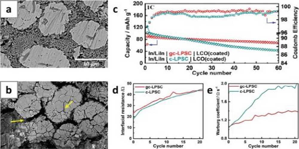
Figure 7. Cross-sectional SEM images of NCA electrodes in ASSB (a) before cycling and (b) after the first charge. (c) Cycling performance of LCO/Li-In batteries using glass-ceramic-Li6PS5Cl and crystalline Li6PS5Cl. (d) Interfacial resistance between lithium cobaltate and solid state electrolyte and (e) Warburg coefficient of ASSBs. Crystalline Li6PS5Cl or glass ceramic Li6PS5Cl was used as the cathode.
In addition to the volume shrinkage of CAM, the oxidative decomposition of sulfide SE also accelerated the delamination of CAM/SE. As shown in Fig. 3e, the oxidation of the sulfide SE and the corresponding volume shrinkage create a void between the CAM and SE.
This neglected source of parasitic CAM/SE detachment can be eliminated by using chloride SE, which is known to be electrochemically stable up to 4.3 V (vs. Li/Li+).
Figure 8a shows the initial charge-voltage curves and corresponding DEP results for composite electrodes using Li6PS5Cl0.5Br0.5 and Li3YCl6.
The composite electrode using Li6PS5Cl0.5Br0.5 experienced a clear pressure release upon initial charging, which was further clarified in the DEP (dP/dQ) plot (Fig. 8a).
This sudden drop in stacking pressure is caused by the oxidative decomposition of Li6PS5Cl0.5Br0.5. In sharp contrast, the electrode using Li3YCl6 showed no initial pressure drop, suggesting no electrochemical-mechanical effect originating from SE oxidation.
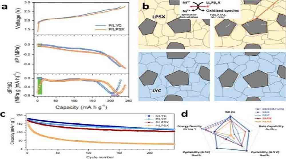
Figure 8. (a) Initial charge-voltage curves, corresponding pressure changes, and DEP curves of polycrystalline NCA electrodes using Li3YCl6 (LYC) or Li6PS5X (LPSX). (b) Schematic illustrating the different microstructures and interfacial evolution of cathodes in ASSBs, as a function of the type of SE (LYC and LPSX). (c) Comparison of ASSB cycle retention using different CAM (poly or single) and SE (LYC or LPSX). (d) Comparison of cell performance using different CAMs (polycrystalline and monocrystalline) and SE (LYC and LPSX).
In conclusion, the volume change of the CAM upon cycling induced electrochemical-mechanical failure, internal cracking of the CAM particles, and CAM/SE delamination. Furthermore, SE oxidation at the CAM/SE interface creates voids and local stress changes that accelerate CAM/SE delamination (Fig. 8b).
Therefore, rational electrode design is necessary to mitigate these mechanical failures. Recently, Jung and colleagues systematically compared composite electrodes composed of single/polycrystalline CAM and sulfide/chloride SE.
As shown in Fig. 8c, the best capacity retention was achieved when single-crystal CAM and chloride SE were used. However, it was noted that a higher weight of SE is required due to the relatively larger weight density of chloride SE (Li3YCl6: 2.43 g cm-3) than sulfide SE (Li6PS5Cl0.5Br0.5: 1.96 g cm-3) Fraction.
Therefore, the discovery of chloride solid state electrolyte using lighter elements, and better distribution of chloride solid state electrolyte through downsizing and/or coatings on CAMs, will greatly facilitate their practical use in ASSBs. Figure 8d shows a detailed performance comparison of these combinations.
The challenge of the battery stack
Changes in electrode and stack volume
Depending on the externally applied pressure (Po), the cell stack pressure (Pstack = Po + ΔPstack) and the cell elements respond differently to the internally evolved stress. Figure 9a shows a schematic diagram of the cell size change of NCM/Li cells under different applied pressures, where the volume change of metallic lithium exceeds that of the NCM electrode.
For simplicity, many factors such as void generation (such as CAM and SE cracking) and pore filling (such as Li deposition in porous SE layers) are ignored. When the applied pressure is too high, the volume expansion of the cathode and metal lithium is suppressed, and the battery volume tends to be limited.
In this case, the state of charge (SOC) change of the battery mostly turned into the accumulation of internal stress, which accelerated the cracking of the CAM particles and SE layer.
In particular, the deposition process of Li generates localized stress that induces the cracking of dense SE grains, although metallic Li is much softer (E = 7.82 GPa) than sulfide SE (E = 23.3-29.0 GPa).
Because in volume-constrained batteries, the stress generated in the electrodes cannot be relieved by changes in the battery size, so the battery is prone to fracture under high external pressure.
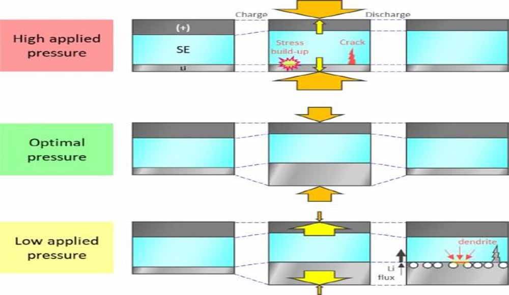
Figure 9. Schematic diagram illustrating the dimensional change of an ASSB cell according to externally applied pressure.
When no external pressure is applied, the cathode and metallic lithium are allowed to expand easily, and the total volume of the stack is free to increase upon charging (Fig. 9). Therefore, only negligible internal stress will be built up. However, at this low working pressure, the inter-particle contacts of the CAM/CAM (for e-transport) and CAM/SE (for Li+ transport) particles in the cathode are easily loosened, which increases the electrode resistance. In addition, the interfacial area of Li|SE is also significantly reduced due to the reduced plastic deformation rate of metallic lithium.
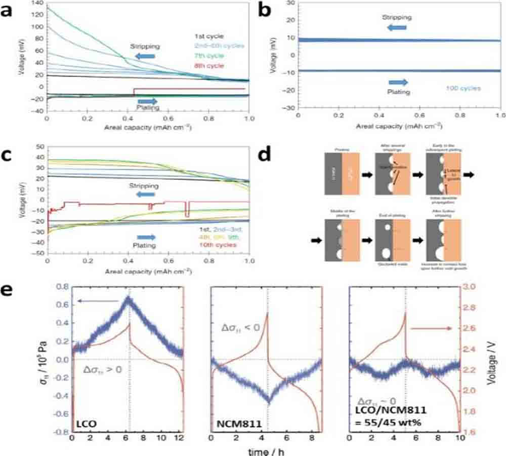
Figure 10. Voltage curves for repeated plating/stripping of metallic lithium measured using a three-electrode cell at different current densities and pressures. (d) Schematic illustration of the Li|Li6PS5Cl interface, cycling at a bulk current density above the critical current density. (e) Comparison of stack pressure changes for CAM|SE|Li4Ti5O12 cells using LiCoO2, NCM811, and a mixture of LiCoO2 and NCM811.
Bruce and his colleagues observed Li plating/stripping behavior at low external pressure (3MPa) using a three-electrode cell. At this mild pressure, after repeated cycling, the overpotential (current: 1 mA cm-2) of lithium stripping gradually increased, especially at the end of the stripping, while the overpotential of the lithium plating process did not change (Fig. 10a).
After a few more cycles, the battery had an internal short circuit. When a higher external pressure of 7 MPa was applied, the reversible lithium plating/stripping could reach 100 cycles (Fig. 10b), while a short circuit was observed at a current density of 2 mA cm-2 (Fig. 10c). This observation suggests that the exfoliation behavior of lithium determines the critical current density for dendritic lithium growth and that it is heavily influenced by the applied pressure.
Figure 10d illustrates the proposed failure mechanism for metallic lithium anodes at low applied pressures. Since metallic lithium cannot deform under these conditions, the voids created by lithium exfoliation cannot be replenished, and the contact area of the lithium-SE layer is reduced.
In the subsequent electroplating, the deposition of lithium starts at three points of metallic lithium, SE layer and voids. Although the voids are laterally filled and occluded by the deposited Li, dendritic Li growth is expected due to the concentrated Li flux to the remaining Li|SE interface.
However, when too high external pressure is applied (e.g., >25MPa), SE layer cracking is caused by metallic lithium deposition, and internal short circuit occurs after applying initial stacking pressure (Pstack = 75MPa) or after relatively short cycles time (Pstack = 25MPa).
Recently, McDowell and colleagues performed a comprehensive study of Li|SE|Li batteries based on real-time stacking pressure measurements, demonstrating that the degree of initial stacking pressure has a critical effect on the morphology and electrochemical behavior of the Li|SE interface.
Likewise, the reversibility and rate capability of tin electrodes are also affected by the applied pressure, where the transformation between Li7Sn3 and LiSn is particularly sensitive to pressure. Therefore, it is crucial to find an optimized stacking pressure range for stable cycling of ASSBs utilizing the Li plating/stripping process.
When utilizing state-of-the-art CAMs, volume changes of active materials and corresponding local stress changes during cycling are unavoidable. Nonetheless, the stress variation (ΔPcathode) of the cathode can be controlled by mixing different CAMs.
As shown in Figure 10e, the stacking pressure changes during charging are positive and negative for LCO|LTO and NCM811/LTO cells, respectively. By mixing LCO and NCM811 in a weight ratio of 55:45, ΔPcat was adjusted to be flat.
In addition to electrode engineering to minimize stress evolution, battery design considering “pressure crosstalk” between cathode and anode will be a very important topic that has so far not been studied in depth.
To optimize ASSB cells with respect to stacking pressure changes, multiple parameters should be considered, such as the type and combination of cathode and anode, n/p ratio (area-capacity ratio of anode and cathode), pressure crosslinking, and the corresponding stress experienced by the SE layer.
For polymer-based solid state electrolyte, the electrochemical-mechanical effects of the Li-SE interface have always been an important topic. After Monroe and Newman proposed a baseline criterion for the suppression of dendritic growth when the shear modulus of SE is greater than twice that of metallic lithium, many research efforts have been devoted to enhancing the mechanical properties of SPE.
Although the resistance of cathode composites utilizing SPE is mainly affected by the preparation conditions, the degree of stacking pressure is crucial for the Li|SPE interface from the perspective of micromechanics, contact area, and interfacial resistance.
The detection of ΔPstack during cycling can be used to diagnose the SOC state of the full battery. Jung and colleagues demonstrated that operational DEP can accurately estimate the SOC of NCM|graphite full cells. To verify the conversion of stack pressure changes into SOC, the operator’s load measurement system was combined with an all-solid-state three-electrode battery.
Figure 11a–c show the voltage curves and pressure changes (ΔPGr) of NCM|graphite cells with different n/p ratios. ΔPGr was estimated by subtracting the pressure change of the NCM|LTO battery from the pressure change of the NCM|Gr battery (ΔPGr = ΔPNCM|Gr-ΔPNCM|LTO). During charging, the local minimum points of the dPGr/dt versus time curves for each n/p ratio in Fig. 11a-c are indicated by red markers.
Singular points are also observed during discharge as local maxima in the DEP map. Notably, as the n/p ratio increases, the local minimum shifts positively on the x-axis, reflecting a greater initial irreversibility.
Instead, the local minimum and maximum points can serve as milestones for tracking SOC, which is verified by matching the actual SOC with these singularities (Fig. 11d–f). This non-destructive diagnostic technique may benefit the development of practical battery management systems for ASSB.
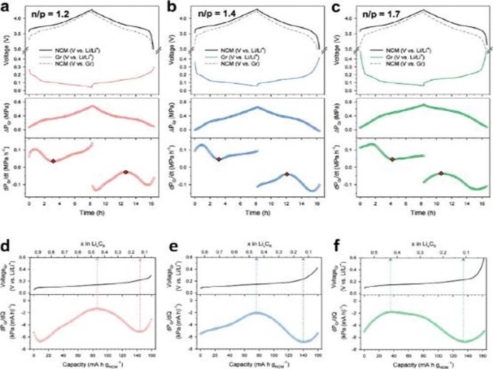
Figure 11. DEP results of NCM/graphite full cells with n/p ratios of (a) 1.2, (b) 1.4, and (c) 1.7.
Operation under mild pressure-charge transport in electrodes
In composite electrodes using LEs, the Li transport behavior is insensitive to external pressure due to the mobility of LEs. Furthermore, large amounts of carbon additives can be added (if desired) without interfering with the Li+ pathway, eliminating the need for strong external pressure. For composite electrodes for ASSBs, the efficient charge transport (Li+ and e-) is severely affected by the external pressure level. Types of Li transport in composite electrodes include long-range ionic conduction along SE particles and charge transfer at the CAM/SE interface. The former is strongly influenced by the initial electrode formation pressure, while the latter is in a dynamic state during cycling because the volume of the active material is constantly changing. Since carbon additives hinder Li+ transport, the amount used is limited. Therefore, the electron conduction pathway mainly relies on the interconnection of CAM particles, which is expected to be sensitive to external pressure given the brittleness of CAM.
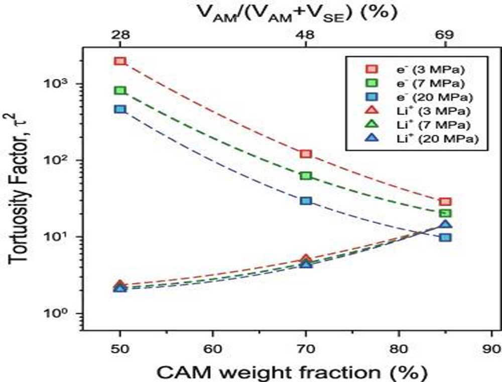
Figure 12. Curvature factors (τ2) of e- and Li+ conductivities for composite electrodes prepared by mixing NCM88 and LPSCl in weight ratios of 50:50, 70:30, and 85:15.
Conclusion and outlook
In summary, focusing on the use of inorganic solid state electrolyte, a hierarchical review of the mechanical properties of solid state electrolyte, the sources of internal stress generation in ASSBs, and their electro-mechanical effects on the various components of ASSBs is carried out.
Despite the ductility of sulfide or halide solid state electrolyte, their inelasticity cannot fully comply with the evolution of internal stress, resulting in some electrochemical-mechanical failures such as detachment of CAM/SE, isolation of CAM primary particles, and challenge to stacking pressure , these failures are much more complex than those discussed in this article.
In addition to materials engineering, the interaction between external and internal stress and the challenges of mild pressure operation are discussed.
We propose the search for novel CAMs with more mechanical compliance and electrode engineering, such as binder/carbon optimization, as an important topic for future research.
Such solutions could impart elastic mechanical properties to composite electrodes and mitigate electrochemical mechanical failures. Besides the isostatic pressing technique, a feasible large-scale fabrication method of ASSBs using inorganic SE is also essential for commercialization, where the mechanical properties of electrodes and separators are important parameters.
Overall, despite some recent achievements in SE materials, protective layers, and electrode optimization in ASSBs, understanding the electro-mechanical behavior in ASSBs and achieving state-of-the-art ASSB performance under realistic operating conditions will be a daunting task and challenge. But there are already some battery manufacturers making solid state batteries, you can read top 10 solid-state battery companies to learn more.