
Background
Although its voltage window is as high as 4.3V, at such a high voltage battery, the structural degradation of the cathode material itself and the side reactions at the cathode-electrolyte interface are serious, so it is necessary to maintain the voltage margin to avoid the rapid degradation of cathode performance, that is, the charge cut-off voltage VCHARGE less than 4.3V.
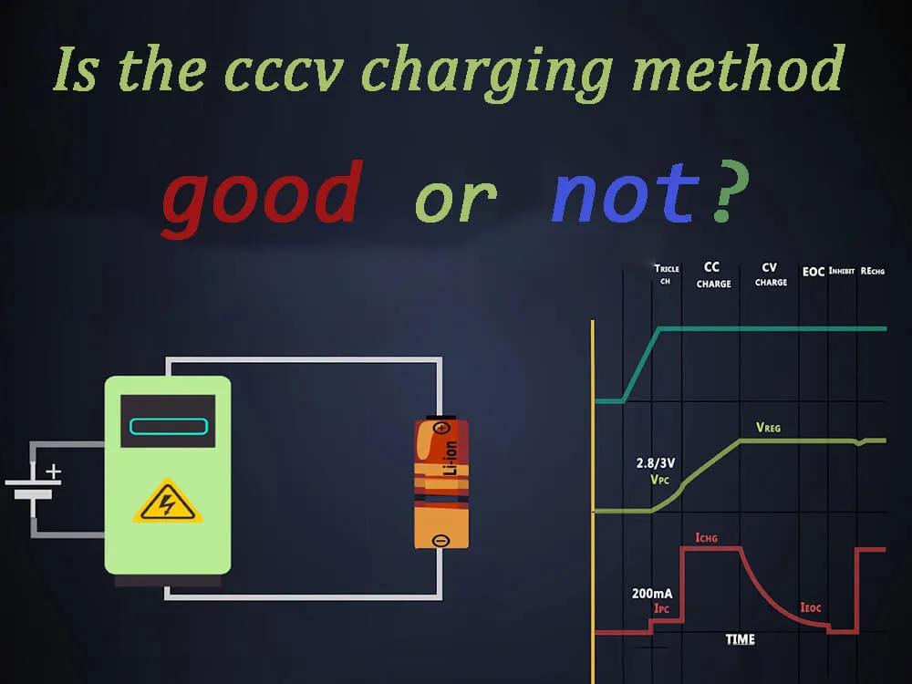
However, maintaining the voltage margin leads to a reduction in the energy density of the cathode material as well as the overall batteries. To compensate for this shortcoming, an additional constant voltage (cv) step can be added after the constant current (CC) charging step to reach a certain voltage;
This strategy is called cccv charging. During the cv step, a certain voltage is maintained until the current drops below a certain level, so the cv step removes extra lithium ions from the cathode particles and alleviates the inhomogeneity of lithium distribution inside the cathode. The following video explains cccv charging battery charger.
The development of new cathode materials and charging protocols requires an understanding of the material’s decay behavior under high-rate CC and cccv charging conditions without maintaining voltage margin. However, no in-depth study of the chemical and crystal structure changes of cathode materials after long cycles under conditions of deep lithium deintercalation has been performed.
At present, it is widely believed in the industry that the degradation of electrochemical performance is caused by the migration and reduction of nickel to Ni2+.
Introduction
A professor at the Korea Institute of Science and Technology revealed the capacity, charging voltage, and capacity of commercial high-nickel cathode materials when cycled through two different charging protocols (constant current charging and constant current and constant voltage cccv) without voltage margin. and the degradation mechanism of discharge voltage.
When the constant current is repeatedly charged, the cathode material becomes aperiodic cation mixing state, and the voltage decay is low. During cccv charging, the cathode material changes from a layered structure to a periodic cation-mixed spinel phase, and the voltage decays seriously.
The electrochemical performance decay is due to the decrease of the equilibrium electrode potential and the increase of the overpotential, which is exacerbated in the periodic cation mixing state.
Next, let’s look at the specific impact of cccv charging
The difference between cc and cccv charging methods

[Figure 1] Morphological, chemical and structural characterization of pristine high nickel cathode material.
a) Scanning electron microscope (SEM) image of pristine hi-ni cathode microspheres and b) corresponding energy dispersive X-ray spectroscopy (EDS) image.
c) annular dark-field STEM image of pristine hi-ni cathode and d) corresponding selected area electron diffraction patterns from “1”, “2” and “3” particles. EEL spectra of e) NiL2,3,f)O K, g)Mn L2,3 and h)CoL2,3 in pristine hi-ni cathode. i) The distribution of the Ni3+/Ni2+ intensity ratio corresponding to (c).
To determine the mechanism of electrochemical performance degradation of high-Ni cathode materials during CC and cccv charging protocols, High nickel cathode material was selected as the cathode material. The selected samples were in the form of microspheres, consisting of many primary particles (Fig. 1a). Within the particle, all TMs were uniformly distributed (Fig. 1b).
Selected area electron diffraction (SAED) and X-ray diffraction (XRD) confirmed that NCM has a hexagonal layered structure of R3¯m (Fig. 1c,d). The valences of Ni, Mn, and Co are 3+/2+, 4+, and 3+, respectively, and Ni3+ and Ni2+ coexist uniformly in the pristine state (Fig. 1e–i).

[Figure 2] The electrochemical performance of NCM83 under different charging conditions. Charge-discharge curves of NCM83 under a) cccv charging and b) CC charging conditions. c) Energy densities of NCM83 (cccv charging) and NCM83 (CC) during 200 cycles. The inset in (c) is the energy efficiency of the same cell during 200 cycles. d) Average charge and discharge voltages of NCM83 (cccv charging) and NCM83 (CC) during 200 cycles.
The High nickel cathode material half-cell was charged and discharged at 1C for 200 cycles using CC or cccv charging (Fig. 2). During the initial cycling, the cells under cccv charging conditions had a 4.2% higher capacity than those under CC conditions (195.3 mAh g−1 for cccv charging and 187.4 mAh g−1 for CC) due to the increased Li extraction from the cv step (Fig. 2a). ,b).
Within 62 cycles, the difference in energy density between these two charging modes is insignificant. But after the 62nd cycle, compared with CC charging, cccv charging showed a more severe decrease in cell energy density and energy efficiency (Fig. 2c) due to an increase in average VCHARGE and a decrease in average VDISCHARGE (Fig. 2d).
During 200 cycles of cccv, the average VCHARGE increased from 3.95V to 4.23V, and the average VDISCHARGE decreased from 3.75V to 3.20V. After 200 cycles, the final average VCHARGE ≈ 3.96V and the final average VDISCHARGE ≈ 3.45V of the batteries under CC conditions are 6.8% lower and 7.3% higher than the final average VCHARGE of the batteries under cccv charging conditions.
Furthermore, the batteries capacity under cccv charging condition (114 mAh g−1) is reduced by about 4.2% after 200 cycles compared to that under CC condition (119 mAh g−1).
The results show that after 200 cycles, the energy density of the batteries under cccv charging condition ≈ 364.4Wh kg−1, and the energy efficiency ≈ 76.3%, which is about 12.6% lower than that of the batteries under CC condition (417.0Wh kg−1, energy efficiency 85.8%) and 11%.
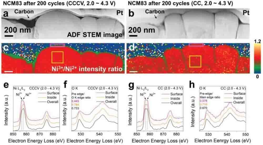
[Figure 3] Chemical analysis of NCM83 after 200 cycles. a) ADF-STEM images of NCM83 (cccv) and b) NCM83 (CC). c) Corresponding Ni3+/Ni2+ intensity ratio profiles for NCM83 (cccv charging) and d) NCM83 (CC). e) NiL2,3 and f) OK edge EEL spectra of NCM83 (cccv charging). g) NiL2,3 and h) OK edge EEL spectra of NCM83 (CC).
To explore the different performance decay mechanisms under the two charging conditions, chemical analysis of TM and oxygen in High nickel cathode material after 200 cycles under CC and cccv charging conditions was performed using EELS (Fig. 3) to test whether the two samples experienced cationic (Ni) shuffle. To effectively visualize Ni reduction in the particles, annular dark field (ADF) STEM images of NCM83 and corresponding Ni3+/Ni2+ intensity ratio distribution maps were acquired (Fig. 3a–d).
Compared with the pristine state, Ni in both samples was significantly reduced after 200 cycles (Figs 1i and 3c,d). In particular, Ni is reduced more on the particle surface than in the interior (Fig. 3e,g), so the front/main edge intensity ratio of the particle surface is lower than that in its interior (Fig. 3f,h). The strength before the edge is related to the unoccupied hole state in the 3d-2p hybrid orbital.
Overall, the Ni in NCM83(CC) was more reduced than that in NCM83(cccv charging). Therefore, more Ni atoms move and shuffle in the Li layer in NCM83(CC) compared to NCM83(cccv charging). The ratio of front/main edge intensity of OK edge in NCM83(CC) is lower than that in NCM83(cccv charging); this difference further proves that Ni in NCM83(CC) is more reduced than that in NCM83(cccv charging) (Fig. 3f,h).
Although NCM83(CC) showed better electrochemical performance than NCM83(cccv charging), the reduction of Ni ions was more in hi-ni cathode(CC) than in hi-ni cathode(cccv charging). This is contrary to the conventional wisdom that the amount of Ni reduction and migration is proportional to the electrochemical performance degradation.
Compared with hi-ni cathode (cccv charging), the Ni3+/Ni2+ ratio is more uniform from surface to interior in hi-ni cathode(CC). In hi-ni cathode(CC), there is almost no difference in the Ni2+ intensity and the ratio of the front/main edge intensity of the OK edge between the particle surface and the interior, while in hi-ni cathode(cccv charging), the difference is obvious.
The severe reduction of Ni on the surface of hi-ni cathode (cccv charging) may lead to the severe degradation of electrochemical performance during cccv charging. This difference indicates that cccv charging at a high voltage of 4.3 V increases the uniformity of the Ni3+/Ni2+ distribution.
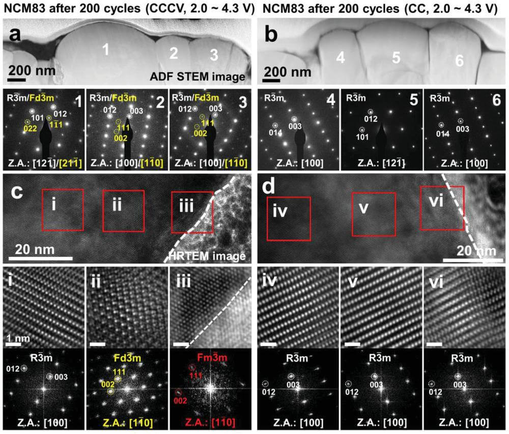
[Figure 4] Structural evolution of NCM83 (cccv charging) and NCM83 (CC) after 200 cycles. a) ADF-STEM images of hi-ni cathode (cccv charging) and b) hi-ni cathode (CC) and the corresponding SAED patterns of the particles (1-6). HRTEM images of c) hi-ni cathode (cccv charging) particle No. 2 and d) hi-ni cathode (CC) particle No. 4 and the corresponding enlarged HRTEM images and fast Fourier transform (FFT) modes (i-vi).
To investigate the differences in crystal structure evolution, ex situ TEM was used. To obtain crystal structure information at the microscopic scale, SAED patterns of the primary particles were acquired (Fig. 4).
The results showed that after 200 cycles, hi-ni cathode (cccv charging) formed a spinel phase (Fd3¯m), and additional diffraction spots appeared in the SAED pattern, representing the layered phase (R3¯m) (Fig. 4a).
This result indicates that the shuffled Ni2+ is periodically arranged in the Li layer. However, although the reduced state of Ni in hi-ni cathode(CC) is lower than that in hi-ni cathode(cccv charging), hi-ni cathode(CC) does not show the additional diffraction spots that hi-ni cathode(cccv charging) possesses; This indicates that in hi-ni cathode(CC), the reduced Ni atoms in the Li layer are not periodically arranged but randomly distributed (Fig. 4b).
This apparent difference between hi-ni cathode(CC) and hi-ni cathode(cccv) may be due to the fact that hi-ni cathode(cccv) was exposed to 4.3 V longer than hi-ni cathode(CC) during long cycling and (cccv) with too much Li inserted.
In the cv step, long exposure to high pressure allows sufficient time for the reduced Ni in the Li layer to undergo periodic alignment, while under CC conditions, the time under high pressure is too short to allow this periodic alignment to proceed, so Li The reduced Ni ions in the layer are randomly distributed.
In cccv charging condition,differences in nickel chemical states on the particle surface and inside of NCM83(cccv) suggest that the crystal structure may vary with particle depth. Therefore, HR-TEM was employed to characterize the crystal structure (Fig. 4c,d). The results confirmed the formation of a rock-salt-like phase (Fm3¯m) on the surface of NCM83 (cccv).
In cccv charging condition, the crystal structure of NCM83(CC) showed no significant difference between the surface and the interior. The surface of NCM83 (CC) is a non-periodic cation-mixed layered structure, which is the same as the particle interior. Periodic cation shuffling in NCM83(cccv) exacerbates the decrease in mean VDISCHARGE and the increase in mean VCHARGE.

[Figure 5] Changes in equilibrium voltage, overpotential and operating voltage after 200 cycles of cccv and CC charging. a) Equilibrium voltage (VEQ), b) overpotential (η), and c) operating voltage (VOP) changes for NCM83 (cccv) and hi-ni cathode (CC) compared to pristine high nickel cathode material. d) The degree of electrochemical performance degradation in different cation mixing states after 200 cycles in cccv charging and CC modes.
To investigate the performance decay mechanism in detail, the equilibrium voltage (VEQ), operating voltage (VOP) and overpotential η (=VEQ– VOP) (Figure 5).
In the absence of periodic Ni shuffling (i.e., hi-ni cathode(CC)), relatively small structural changes reduce the VEQ of pristine high nickel cathode material by ≈0.16 V at the beginning of discharge, hindered Li diffusion, and increase η by ≈0.15 V at mid-discharge (Fig. 5a-c).
In contrast, in high nickel cathode material with Ni periodically shuffled (cccv), the decrease in VEQ and the increase in η were 2-fold and 3-fold, respectively, compared with pristine high nickel cathode material. The limited reversibility of TM migration allows the continuous formation of a spinel-like phase, leading to voltage decay. Therefore, the periodic arrangement of Ni in hi-ni cathode (cccv) severely reduces VEQ and increases η, which significantly degrades the electrochemical performance (Fig. 5d).
Summary and outlook

This work investigates the structure and chemical degradation mechanism of a high-nickel cathode material (NCM83) during long-term electrochemical operation without voltage margin. Using cv charging at 4.3V causes Ni atoms to periodically align in the Li layer after migration, which severely hinders Li diffusion, increases overpotential, and reduces the electrode potential of the material, so its energy density is severe reduce. Now many companies are supplying high nickel materials such as Top 5 NCM811 high nickel ternary cathode material companies.
To avoid the periodic arrangement of nickel in the lithium layer, cccv charging should be avoided unless sufficient voltage margin is maintained. The cccv charging findings provide valuable insights into the practical application development of high-Ni cathode materials.
References to cccv research literature: https://onlinelibrary.wiley.com/doi/10.1002/aenm.202201151